
Flexible force sensor calibration test platform and method

A test platform and force sensor technology, which is applied in the field of sensor calibration, can solve problems such as the inability to calibrate the influence of shear stress, and achieve the effect of eliminating shear stress

Active Publication Date: 2020-05-22
叶强 +3
View PDF10 Cites 0 Cited by
  • Summary
  • Abstract
  • Description
  • Claims
  • Application Information

AI Technical Summary

Problems solved by technology

[0016] However, the above technical solutions cannot calibrate the influence of shear stress on the flexible force sensor, and it is urgent to develop a device that can meet this requirement

Method used


Image

  • Flexible force sensor calibration test platform and method
  • Flexible force sensor calibration test platform and method
  • Flexible force sensor calibration test platform and method

Examples


Embodiment 1

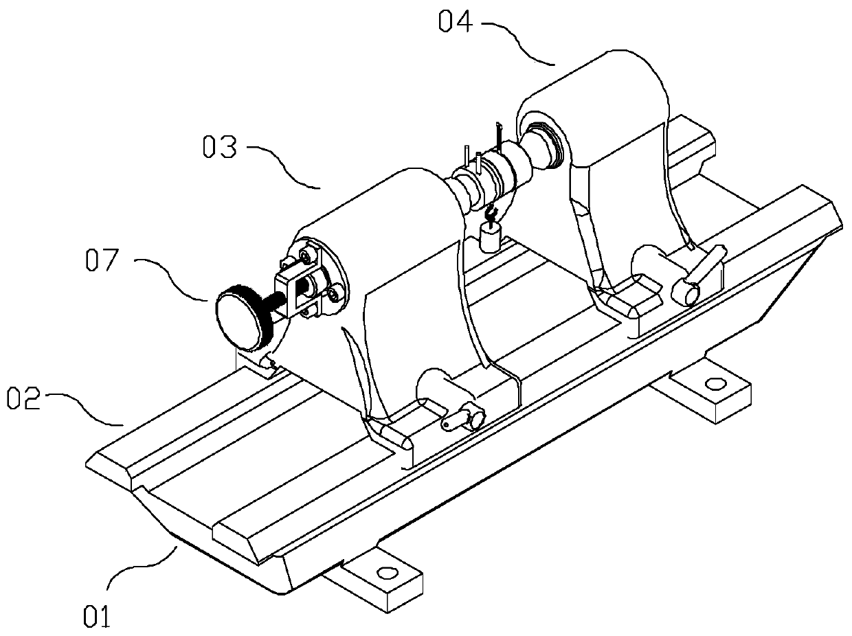
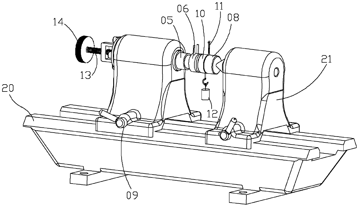
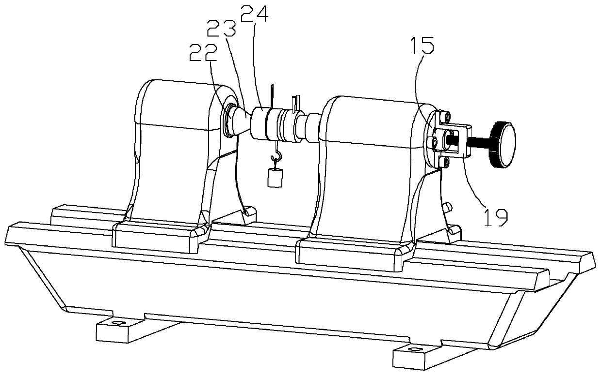
[0053] like Figure 1 to Figure 4 As shown, the flexible force sensor calibration test platform of this embodiment includes a platform-shaped base 01, the base 01 has a horizontal rail 02, a first sliding seat 03 and a second sliding seat 04, the first sliding seat 03 and the second sliding seat 04 The sliding seat 04 forms a horizontal sliding pair with the horizontal track 02 respectively; the first sliding seat 03 has a channel 16, and one end of the channel 16 is provided with a piston column 05, and the end of the piston column 05 protruding from the channel 16 is fixedly connected with a single-dimensional force sensor 06 , the force measuring direction of the single-dimensional force sensor 06 is the horizontal direction, the other end of the channel 16 is provided with an adjusting rod 07, and the channel 16 is provided with a transmission mechanism, and the adjusting rod 07 is connected to the piston rod 05 through the transmission mechanism; the second sliding seat 0...

Embodiment 2

[0062] The calibration method of this embodiment uses the flexible force sensor 11 of Embodiment 1 to calibrate the test platform, and the specific steps include:

[0063] The first step is to fix the first sliding seat 03 on the horizontal track 02 through the locking member 09, so that the single-dimensional force sensor 06 is in a fixed position; slide the second sliding seat 04 along the horizontal track 02 to the first sliding seat 03, and at the same time Place the movable pressing block 10 and the flexible force sensor 11 to be calibrated between the one-dimensional force sensor 06 and the fixed pressing block 08, the flexible force sensor 11 is located between the movable pressing block 10 and the fixed pressing block 08, and the movable pressing block 10 The hook is directly below the movable pressing block 10; when the single-dimensional force sensor 06 and the fixed pressing block 08 clamp the movable pressing block 10 and the flexible force sensor 11, and the output...


PUM


Abstract

The invention relates to a calibration test platform and method of a flexible force sensor. The platform comprises a platform-shaped substrate. The substrate comprises a horizontal track, a first sliding seat and a second sliding seat. The first sliding seat comprises a channel. A piston column is arranged on one end of the channel. The end, stretching out of the channel, of the piston column is fixedly connected with a single-dimensional force sensor. An adjustment rod is arranged on the other end of the channel. A transmission mechanism is arranged in the channel. The adjustment rod is in transmission connection with the piston rod. The second sliding seat comprises a fixing press block. The platform also comprises a moving press block, a to-be-calibrated flexible force sensor and a group of weights with hooks. The moving press block comprises a hook. According to the invention, when a flexible force sensor suffers from cutting stress, the output data can be calibrated; a correctionalgorithm is acquired to eliminate effects caused by the cutting stress; and data of the flexible force sensor is allowed to be approximate to actual conditions during the actual application of the flexible force sensor.

Description

technical field [0001] The invention relates to a flexible force sensor calibration test platform and method, belonging to the technical field of sensor calibration. Background technique [0002] As far as the applicant knows, the measurement of force between contact interfaces is usually realized indirectly through the measurement of pressure, and pressure is usually expressed as the force applied per unit area relative to the surface of the object. Therefore, in order to achieve effective contact force measurement, a good contact surface Control is particularly important, and it is even more important for the complexity of people's contact with the outside world. With the development of sensor technology and the increase in related application requirements, as well as the explosive growth of applications in the field of human motion detection, on the one hand, the performance of sensors represented by flexible force sensors continues to increase; on the other hand, the req...

Claims


Application Information

Patent Timeline
Patent Type & Authority Patents(China)
IPC IPC(8): G01L25/00
CPCG01L25/00
Inventor 叶强高杉高润胡冠宇
Owner 叶强
Learn More