Screw detection mechanism and detection method and automatic production line

A detection mechanism and screw technology, which is applied in the direction of measuring devices, instruments, metal processing, etc., can solve the problem of not being able to accurately detect whether the screw is screwed in place, so as to prevent the reduction of work efficiency, the increase of maintenance costs, and the effect of avoiding loose connections

Active Publication Date: 2018-04-06
SUZHOU CLEVA PRECISION MACHINERY & TECH
View PDF8 Cites 5 Cited by
  • Summary
  • Abstract
  • Description
  • Claims
  • Application Information

AI Technical Summary

Problems solved by technology

[0005] The purpose of the present invention is to provide a screw detection mechanism, detection method and automatic production line to solve the problem in the prior art that it cannot accurately detect whether the screw is screwed in place

Method used


Image

  • Screw detection mechanism and detection method and automatic production line
  • Screw detection mechanism and detection method and automatic production line
  • Screw detection mechanism and detection method and automatic production line

Examples


Embodiment 1

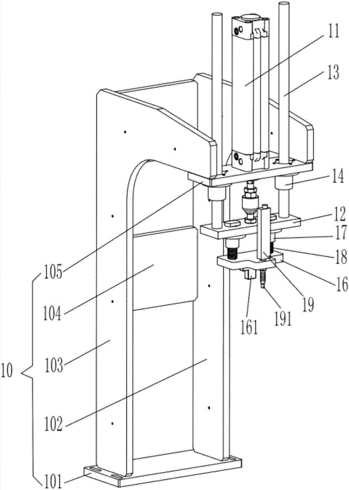
[0038] Such as figure 1 and figure 2 As shown, the present embodiment provides a screw detection mechanism for detecting whether the screw is screwed in place. The screw detection mechanism includes a frame 10, a cylinder 11, a connection plate 12, a detection plate 16, a connection column 15, a detection part 161 and a displacement sensor 19.

[0039] The frame 10 comprises a base plate 101, a first support plate 102, a second support plate 103, a reinforcing plate 104 and a cylinder fixing plate 105, wherein the first support plate 102 and the second support plate 103 are L-shaped, and the first support plate 102 is arranged in parallel with the second support plate 103 at intervals, and the end of the vertical portion of the first support plate 102 away from the horizontal portion and the end of the vertical portion of the second support plate 103 away from the horizontal portion are all fixedly connected to the bottom plate 101; The plate 104 is connected between the ve...

Embodiment 2

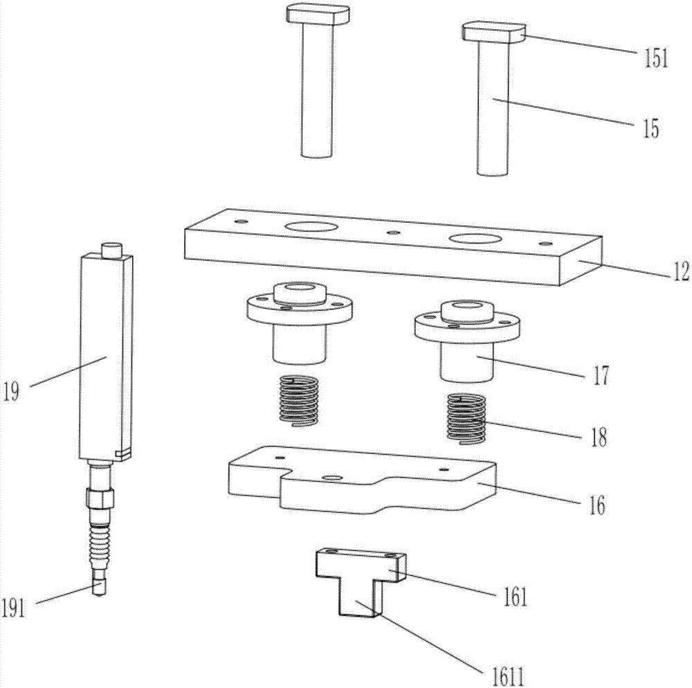
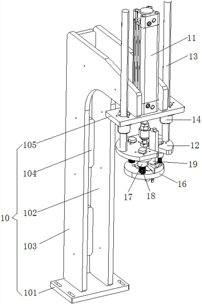
[0049] Such as Figure 3 to Figure 5 As shown, the screw detection mechanism provided in this embodiment is basically the same as that in Embodiment 1, and for the sake of brevity, only the differences from Embodiment 1 will be described. In this embodiment, the screw detection mechanism can detect a plurality of screws at a time, that is, the detection part 161 has a plurality of detection protrusions 1611 . In this embodiment, the detection part 161 has three detection protrusions 1611, and the three detection protrusions 1611 are distributed along the center of the detection part 161 in a circle, and the axis of the piston rod of the cylinder 11 is arranged in line with the center of the detection part 161 Correspondingly, the number of connecting posts 15 is equal to the number of detecting protrusions 1611 , and the connecting posts 15 and the detecting protrusions 1611 are arranged coaxially. In addition, the lower end of the connecting column 15 is connected to the det...


PUM


Abstract

The invention relates to a screw detection mechanism and detection method and an automatic production line. The screw detection mechanism comprises a frame, a driving device, a detection board and a displacement sensor. When a screw is detected, firstly the reading of the displacement sensor is set to be X when the screw is screwed in position; then the driving device drives the detection board tomove down, a contact of the displacement sensor makes contact with the surface of a workpiece first, and the detection board abuts against the top surface of the screw to be detected; then the reading of the displacement sensor is read after the detection board is stable and the reading is compared with X; if the reading is equal to X, the screw to be detected is screwed in position; if the reading is not equal to X, the screw to be detected is not screwed in position; and if the screw is not screwed in position, the screw is screwed in position in time. Therefore, the situation of untight connection between workpieces can be avoided, and the problems of reduced work efficiency and increased maintenance costs due to looseness between the workpieces can be prevented.

Description

technical field [0001] The invention relates to the technical field of electric tools, in particular to a screw detection mechanism and a detection method thereof. Background technique [0002] In the combination of parts, most of the parts need to use screws to fix the combination of multiple parts. In order to improve production efficiency and reduce costs, using automatic equipment for screw locking is a quick solution. The automatic locking screw machine can automatically complete the actions of product transmission, positioning, screw discharge, screw feeding and screw locking, so as to realize all the screws at one time. It has the advantages of simple operation and fast speed. [0003] There are two types of automatic locking screw machines on the market: air batch and electric screwdriver. Among them, the air batch is based on the magnetic switch of the cylinder, the proximity switch and the torque of the screwdriver to detect whether there are floating locks, missin...

Claims


Application Information

Patent Timeline
Patent Type & Authority Applications(China)
IPC IPC(8): B23P19/06B23P19/00G01B21/00
CPCB23P19/00B23P19/06G01B21/00
Inventor 孔钊陈静温伟伟
Owner SUZHOU CLEVA PRECISION MACHINERY & TECH
Why Eureka
Try Eureka