Installation method of camera for improving recognition accuracy

An installation method and camera technology, applied in the field of intelligent parking lots, can solve problems such as troublesome camera adjustment, small adjustment range, and affecting the recognition accuracy of the vehicle recognition system, so as to achieve the best imaging quality and improve the recognition accuracy

Active Publication Date: 2018-04-06
深圳锐视威科技有限公司
View PDF4 Cites 4 Cited by
  • Summary
  • Abstract
  • Description
  • Claims
  • Application Information

AI Technical Summary

Problems solved by technology

[0006] The technical problem to be solved by the present invention is that it is quite troublesome to adjust the camera in the prior art after it is installed, and the adjustment range is small, which affects the identification accuracy of the vehicle identification system. method to solve the above problems

Method used


Image

  • Installation method of camera for improving recognition accuracy
  • Installation method of camera for improving recognition accuracy

Examples


Embodiment 1

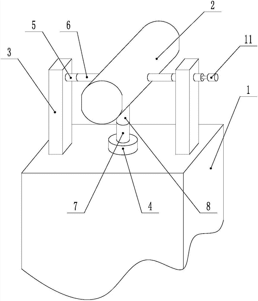
[0026] Such as Figure 1 ~ Figure 2 As shown, the camera installation method for improving recognition accuracy includes the following steps:

[0027] A: Install the camera device 2 on the identification device body 1, install the support frame 3 on both sides of the camera device 2, and install the mounting seat 4 under the camera device 2;

[0028] B: Install the rotating shaft-5 on the support frame 3, the telescopic rod-6 is installed on the rotating shaft-5, and the rotating shaft-5 can rotate around its own axis direction, and the end of the telescopic rod-6 away from the rotating shaft-5 is connected to the camera device 2;

[0029] C: Install the rotating shaft 2 7 on the mounting base 4, install the telescopic rod 2 8 on the rotating shaft 2 7, and the rotating shaft 2 7 can rotate around its own axis direction, and the end of the telescopic rod 8 away from the rotating shaft 2 7 is connected to the camera device 2;

[0030] D: Turn the shaft one 5 to drive the camer...

Embodiment 2

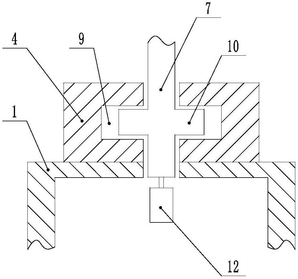
[0033] This embodiment is based on Embodiment 1 to further illustrate the present invention.

[0034] Such as Figure 1 ~ Figure 2 As shown, the camera installation method that is convenient for improving the recognition accuracy is provided with a limiting groove 9 in the mounting seat 4, and a limiting platform 10 is arranged on the rotating shaft 2 7, and the limiting groove 9 and the limiting platform 10 are mutually fitted, and the limiting platform 10 can rotate around the axial direction of rotating shaft 2 7 in the limiting groove 9, and the effect of the limiting platform 10 is to prevent the rotating shaft 2 7 from falling off in the mounting seat 4; One 5 rotates, and driving device one 11 can adopt common driving device on the market, as motor etc.; Common driving devices on the market, such as motors, etc.


PUM


Abstract

The invention discloses an installation method of a camera for improving the recognition accuracy, comprising the following steps: A: installing a camera device on an identification device body, installing support frames on both sides of the camera device, and installing a mounting seat under the camera device; B: installing a first rotating shaft on the support frames and a first telescopic rod on the first rotating shaft; C: installing a second rotary shaft on the mounting seat and a second telescopic rod on the second rotary shaft; D: rotate first rotating shaft to adjust the vertical position of the camera device; E: rotating second rotary shaft to adjust the horizontal position of the camera device. The invention adjusts the installation angle of the camera device through the rotationof the first and second rotating shafts so as to optimize the imaging quality of the camera device and improve the identification accuracy of the vehicle identification system.

Description

technical field [0001] The invention relates to the field of intelligent parking lots, in particular to a camera installation method for improving recognition accuracy. Background technique [0002] The parking lot refers to the place used for parking vehicles. The parking lot can be divided into four types: warm garage, cold room garage, carport and open-air parking lot. The main task of the parking lot is to keep the parked vehicles. With the development of society, there are more and more cars in the city, and the places for centralized storage and management of vehicles are put forward by human beings for the order of vehicle entry and exit, the safety of vehicle storage, and the compensation of vehicle storage management. As a result, intelligent parking lot system products came into being and are playing an increasingly important role in modern parking lot management. The full name of the parking lot system is the intelligent parking lot management system, which is us...

Claims


Application Information

Patent Timeline
Patent Type & Authority Applications(China)
IPC IPC(8): F16M11/04F16M11/12G08G1/017H04N5/225
CPCG08G1/0175F16M11/04F16M11/121H04N23/50
Inventor 杜东平
Owner 深圳锐视威科技有限公司
Why Eureka
Try Eureka