
Optical sensor based on floodlighting function and 3D imaging device thereof

An imaging device and 3D technology, applied in the field of optics and electronics, can solve the problems of single detection distance and range, difficult to meet the needs of light sensors, and difficult to achieve high-precision recognition.

Inactive Publication Date: 2018-04-06
SHENZHEN ORBBEC CO LTD
View PDF11 Cites 25 Cited by
  • Summary
  • Abstract
  • Description
  • Claims
  • Application Information

AI Technical Summary

Problems solved by technology

[0004] With the increasing demand for the functions of smart devices, the functional requirements for light sensors are also increasing, and traditional single-function light sensors are often difficult to meet the demand.
For proximity sensors, it is often only possible to detect whether close objects are approaching, and the detection distance and range are single
For 3D sensors, they are often composed of projection modules and acquisition modules, which take up a lot of equipment space, but can only provide 3D imaging capabilities; and 3D sensors in the prior art cannot perform flood imaging on targets, so in When performing face recognition at night, it is difficult to achieve high-precision recognition
The increase in demand has led to the mechanical addition of corresponding sensors to smart devices, and the effect achieved is often a simple superposition of functions, which has not achieved the effect of integration and fusion to achieve more functions

Method used


Image

  • Optical sensor based on floodlighting function and 3D imaging device thereof
  • Optical sensor based on floodlighting function and 3D imaging device thereof
  • Optical sensor based on floodlighting function and 3D imaging device thereof

Examples


Embodiment Construction

[0027] In order to make the technical problems, technical solutions and beneficial effects to be solved by the embodiments of the present invention clearer, the present invention will be further described in detail below in conjunction with the accompanying drawings and embodiments. It should be understood that the specific embodiments described here are only used to explain the present invention, not to limit the present invention.

[0028] It should be noted that when an element is referred to as being “fixed” or “disposed on” another element, it may be directly on the other element or be indirectly on the other element. When an element is referred to as being "connected to" another element, it can be directly connected to the other element or indirectly connected to the other element. In addition, the connection can be used for both fixing and circuit communication.

[0029] It is to be understood that the terms "length", "width", "top", "bottom", "front", "rear", "left", ...


PUM


Abstract

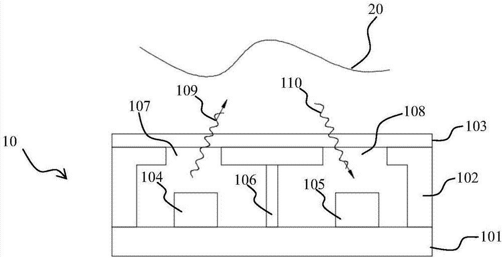
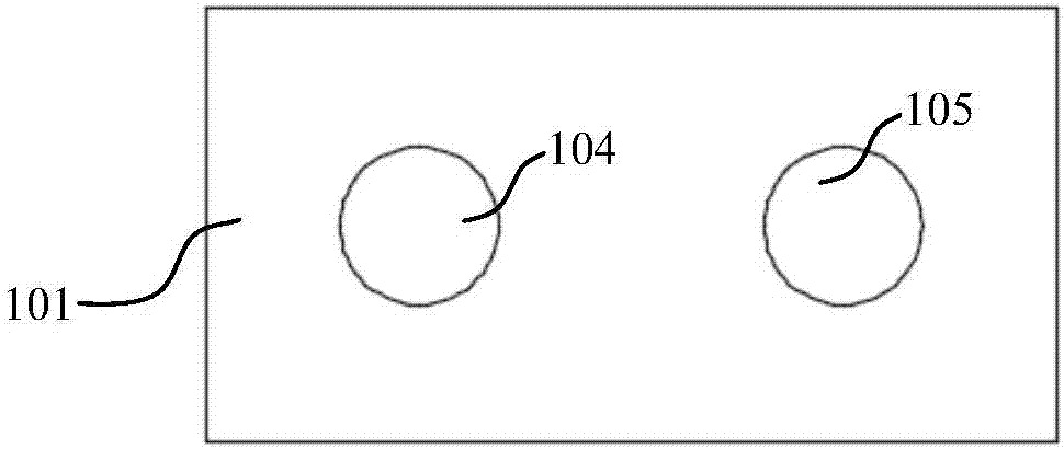
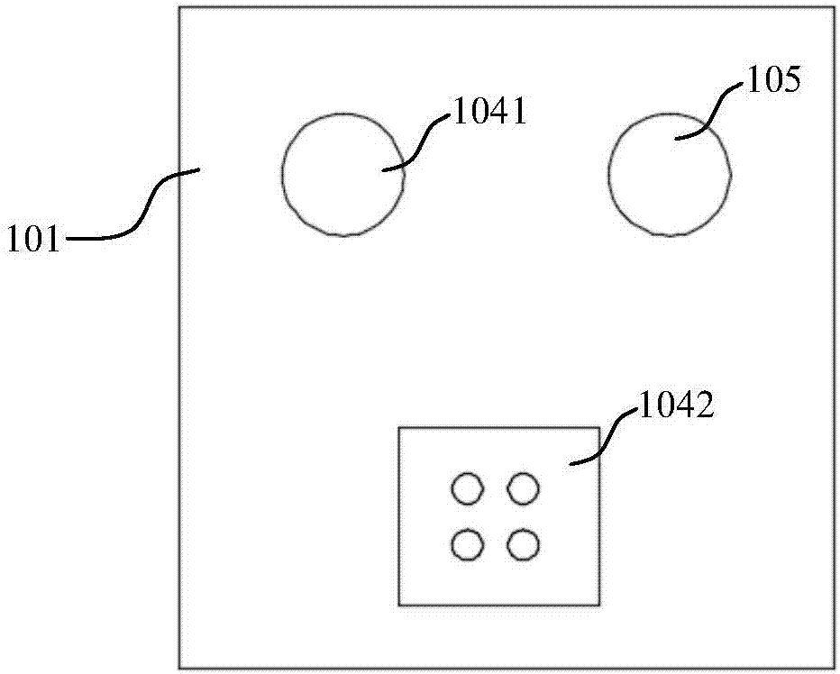
The invention discloses a 3D imaging device, which comprises a projection module, an optical sensor and a first acquisition module, wherein the projection module is used for projecting a patterned beam; the optical sensor comprises a first light transmitting unit for transmitting a first beam, a second light transmitting unit for transmitting a second beam and a light detection unit for detectingthe first beam to judge the approaching distance of an object; and the first acquisition module acquires a first target image illuminated by the patterned beam when the projection module projects thepatterned beam and acquires a second target image illuminated by the second beam when the second light transmitting unit transmits the second beam. Detection on the approaching degree of the object iscarried out through the first beam. The second beam is acquired by the acquisition module in the 3D sensor for providing floodlighting on the 3D sensor. Fusion and superposition of multiple functionssuch as approaching degree detection and floodlighting imaging can be realized.

Description

technical field [0001] The invention relates to the technical fields of optics and electronics, in particular to a light sensor based on a floodlight function and a 3D imaging device thereof. Background technique [0002] Optical sensors have been widely used in smart terminals such as mobile phones, tablets, computers and other devices. In mobile terminal equipment, the ambient light sensor is used to detect the intensity of ambient light so as to further automatically adjust the brightness of the screen. The proximity sensor can detect whether there is an object approaching the device, especially in mobile phones and other devices. The mobile phone is close to the face, and the proximity sensor can detect this phenomenon to control the screen, such as turning off the screen, to prevent the face from accidentally touching the screen. [0003] 3D sensors will also be applied to smart terminal devices, especially 3D sensors based on structured light technology, which can be ...

Claims


Application Information

Patent Timeline
Patent Type & Authority Applications(China)
IPC IPC(8): G01J1/42G01B11/02
CPCG01B11/026G01J1/4204
Inventor 闫敏许星
Owner SHENZHEN ORBBEC CO LTD
Learn More