
Pin control device and method

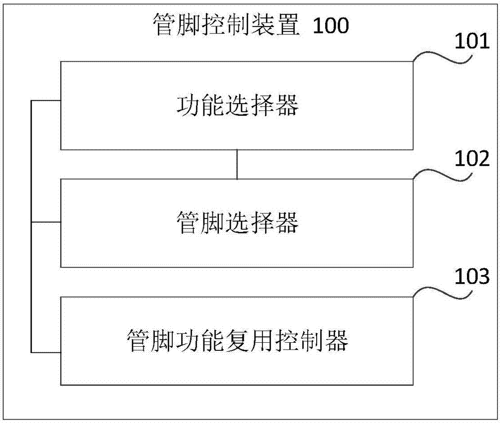
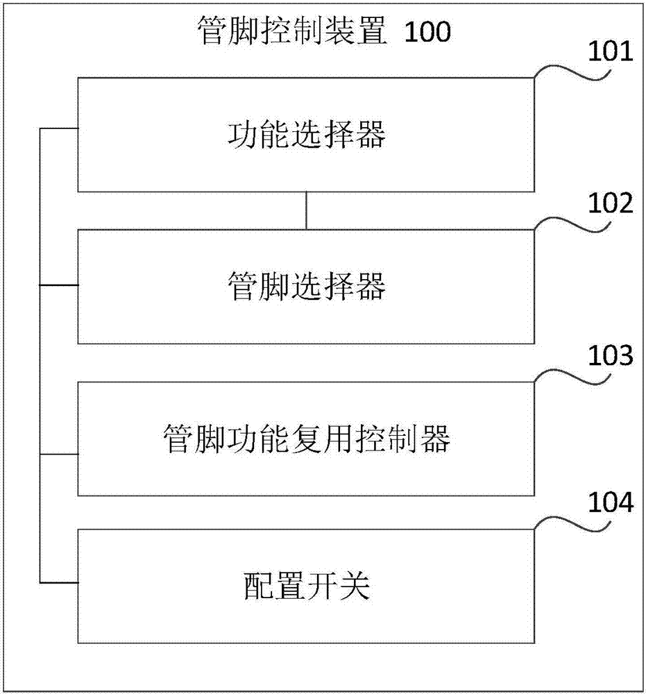
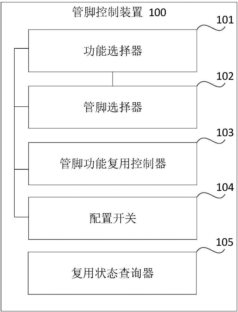
A pin control and pin technology, which is applied in the electronic field, can solve the problems that the pin multiplexing function group cannot be modified and the chip portability is low, and achieve the effect of reducing the development cost.

Active Publication Date: 2018-04-06
BYD SEMICON CO LTD
View PDF6 Cites 2 Cited by
  • Summary
  • Abstract
  • Description
  • Claims
  • Application Information

AI Technical Summary

Problems solved by technology

[0003] The purpose of this disclosure is to provide a pin control device and method to solve the problems that the pin multiplexing function group cannot be modified and the chip portability is low

Method used


Image

  • Pin control device and method
  • Pin control device and method
  • Pin control device and method

Examples


Embodiment Construction

[0047] The specific implementation manners of the present disclosure will be described in detail below in conjunction with the accompanying drawings, examples of which are shown in the accompanying drawings. When the following description refers to the accompanying drawings, the same numerals in different drawings refer to the same or similar elements unless otherwise indicated. The implementations described in the following exemplary examples do not represent all implementations consistent with the present disclosure. Rather, they are merely examples of apparatuses and methods consistent with aspects of the present disclosure as recited in the appended claims.

[0048] Before describing the pin control device and method provided in the present disclosure, the application scenarios involved in the various embodiments of the present disclosure are firstly introduced. The application scenario is an application system including MCU chips, peripheral devices and circuit boards. ...


PUM


Abstract

The invention relates to a pin control device and method and relates to the field of electronic technology. The device comprises a function selector, a pin selector and a pin function multiplexing controller, wherein the function selector is used for determining a to-be-configured target function according to function configuration information; the pin selector is used for determining a to-be-configured target pin according to pin configuration information and determining a target function multiplexing position, which the target function needs to be mapped to, on the target pin; and the pin function multiplexing controller is used for mapping the target function to the target function multiplexing position on the target pin. Through the pin control device and method, a multiplexing function of an external pin of a chip can be freely mapped to a designated position, therefore, the chip can be flexibly used under the condition of not changing any external hardware layout, development cost of a system circuit board can be lowered, development efficiency is improved, and the portability of the chip is enhanced.

Description

technical field [0001] The present disclosure relates to the field of electronic technology, and in particular, to a pin control device and method. Background technique [0002] In today's electronic technology field, MCU (Microcontroller Unit micro control unit) chips are becoming more and more powerful because of their realizable functions, and their application scenarios are becoming more and more extensive. In the application development process of the MCU chip, it is often encountered that the multiplexing function group of a certain pin cannot be modified after being determined. At the same time, if a new MCU chip needs to be used to replace the original chip, the layout of the original system circuit board needs to be re-planned, resulting in low development efficiency, high development cost, and low portability of the MCU. Contents of the invention [0003] The purpose of the present disclosure is to provide a pin control device and method to solve the problems th...

Claims


Application Information

Patent Timeline
IPC IPC(8): G06F13/40
CPCG06F13/4022G06F13/4068
Inventor 周博李奇峰杨云
Owner BYD SEMICON CO LTD
Learn More