
Backlight partition control method and device

A technology of backlight partition and control method, which is applied to static indicators, instruments, etc., to achieve the best display effect

Active Publication Date: 2020-08-18
上海顺久电子科技有限公司
View PDF2 Cites 0 Cited by
  • Summary
  • Abstract
  • Description
  • Claims
  • Application Information

AI Technical Summary

Problems solved by technology

[0005] In order to solve the problem of how to adjust the backlight value of the backlight partition according to different usage scenarios, the embodiment of the present invention provides a backlight partition control method and device

Method used


Image

  • Backlight partition control method and device
  • Backlight partition control method and device
  • Backlight partition control method and device

Examples


Embodiment Construction

[0030] In order to make the object, technical solution and advantages of the present invention clearer, the implementation manner of the present invention will be further described in detail below in conjunction with the accompanying drawings.

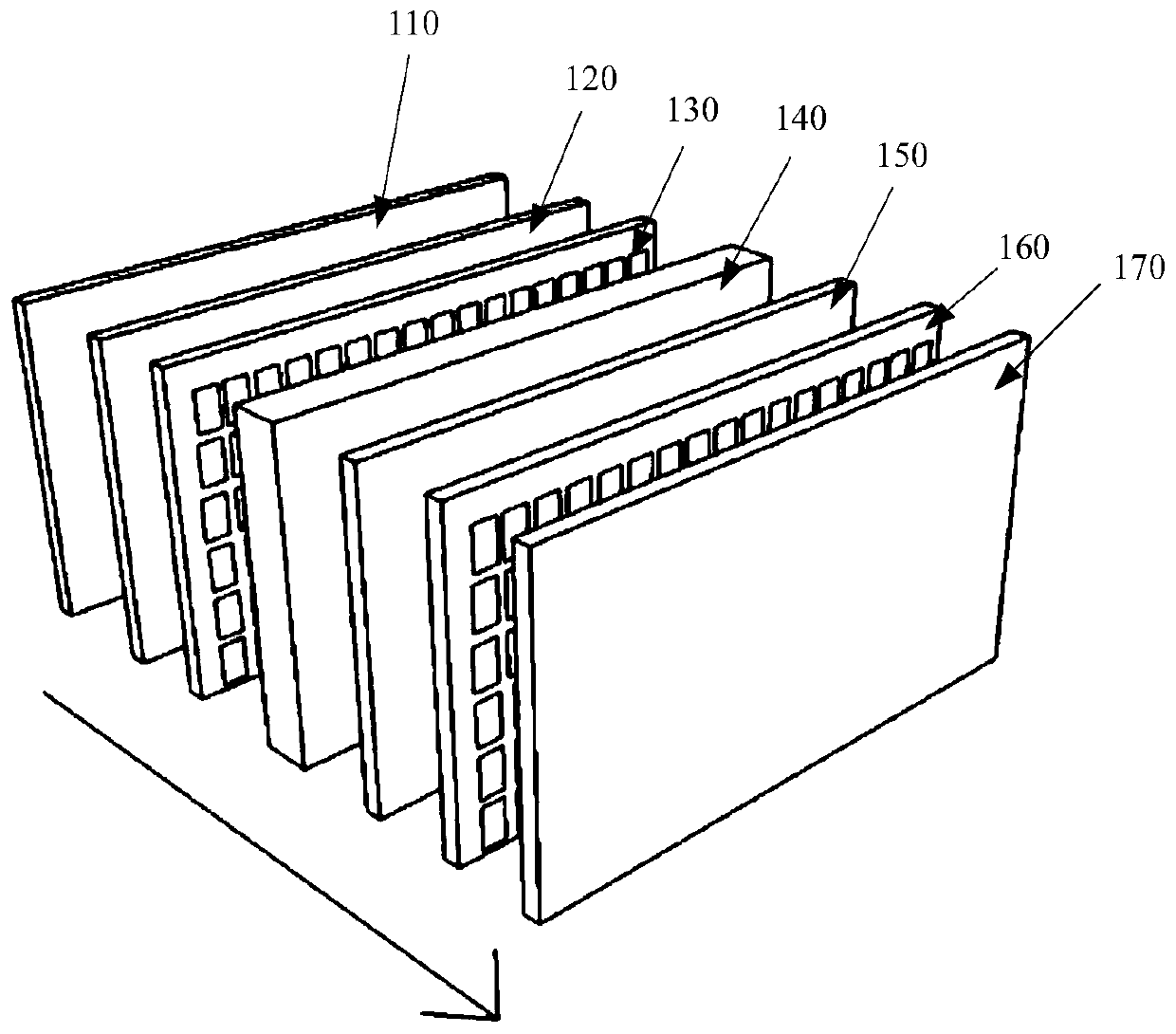
[0031] Before introducing and illustrating the embodiments of the present invention, a brief introduction to an LCD (Liquid Crystal Display, liquid crystal display) panel is firstly made. Please refer to figure 1 , which shows a schematic structural diagram of an LCD panel 100 .

[0032] The LCD panel 100 includes: a backlight layer 110 , a lower polarizer 120 , an array substrate 130 , a liquid crystal layer 140 , an upper substrate 150 , a color filter layer 160 , an upper polarizer 170 and a display chip.

[0033] Wherein, the lower polarizer 120 is located on the upper layer of the backlight layer 110; the array substrate 130 is located on the upper layer of the lower polarizer 120; the liquid crystal layer 140 is located on the u...


PUM


Abstract

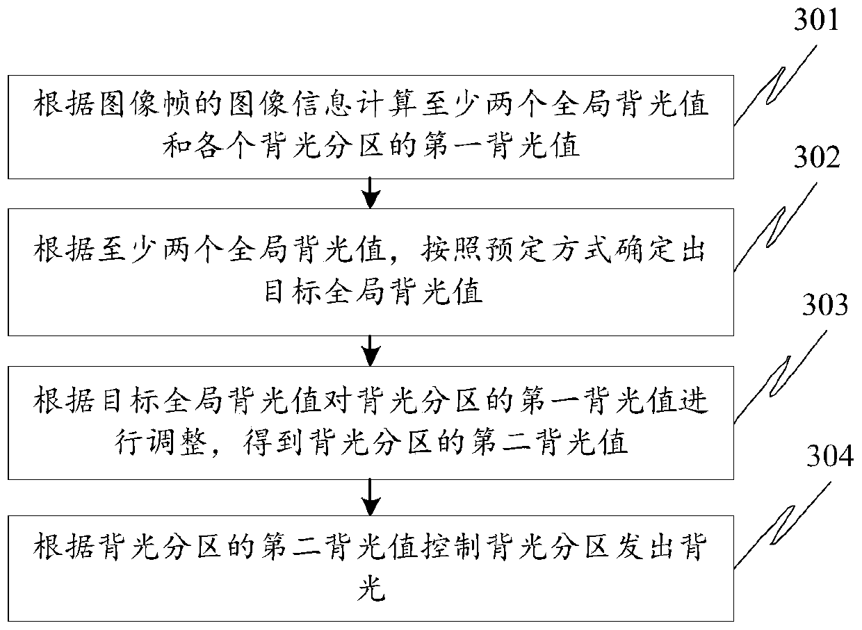
The invention, which belongs to the technical field of liquid crystal, discloses a backlight zone control method and device. The method comprises: at least two global backlight values are calculated according to image information of an image frame; according to the at least two global backlight values, a target global backlight value is determined based on a predetermined mode; a first backlight value of each backlight zone is calculated based on the image information of the image frame; the first backlight values of the backlight zones are adjusted according to the target global backlight value to obtain second backlight value of the backlight zones; and according to the second backlight value of the backlight zones, the backlight zones are controlled to emit backlight. According to the invention, the target global backlight value is determined according to a predetermined manner based on the at least two global backlight values and the predetermined manner is determined based on different scene modes or need modes, so that the backlight values of the backlight zones are adjusted in different scene modes or need modes and thus the optimized display effect of the image frame is realized.

Description

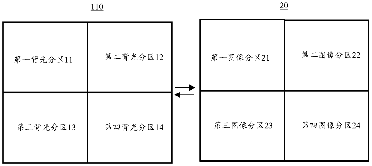
technical field [0001] Embodiments of the present invention relate to the field of liquid crystal display technology, and in particular to a backlight partition control method and device. Background technique [0002] Backlight partition control technology is a technology that divides the backlight layer in the liquid crystal display into M*N backlight partitions, and drives each backlight partition separately. M is the number of backlight partitions in the vertical direction, and N is the backlight partition in the horizontal direction. number. A liquid crystal display includes a liquid crystal layer and a backlight layer, and the backlight layer is a device for providing backlight to the liquid crystal layer. [0003] The current backlight partition control method includes: the display chip acquires the image information of the image frame, the image information includes the pixel value of each pixel, and the pixel value of each pixel includes: R (red, red) component, G (...

Claims


Application Information

Patent Timeline
Patent Type & Authority Patents(China)
IPC IPC(8): G09G3/34G09G3/36
CPCG09G3/3406G09G3/36
Inventor 田广
Owner 上海顺久电子科技有限公司
Learn More