Feeding assembly and coating device

A material supply and component technology, which is applied to devices and coatings that apply liquid to the surface, and can solve problems such as paint adsorption, damage to the air pump, and no immediate stoppage.

Inactive Publication Date: 2018-04-13
梁涛
View PDF6 Cites 8 Cited by
  • Summary
  • Abstract
  • Description
  • Claims
  • Application Information

AI Technical Summary

Problems solved by technology

[0003] The purpose of the present invention is to overcome the above-mentioned deficiencies in the prior art, and to provide a discharge assembly, which aims to solve the problem that when the feeding needs to be stopped, if only the operation of the pneumatic pump is stopped, the feeding will not stop immediately and continue In the case of overflow, if the air pump reversely sucks, it will cause the paint to be adsorbed to the air pump, causing damage to the air pump

Method used


Image

  • Feeding assembly and coating device
  • Feeding assembly and coating device

Examples


Embodiment 1

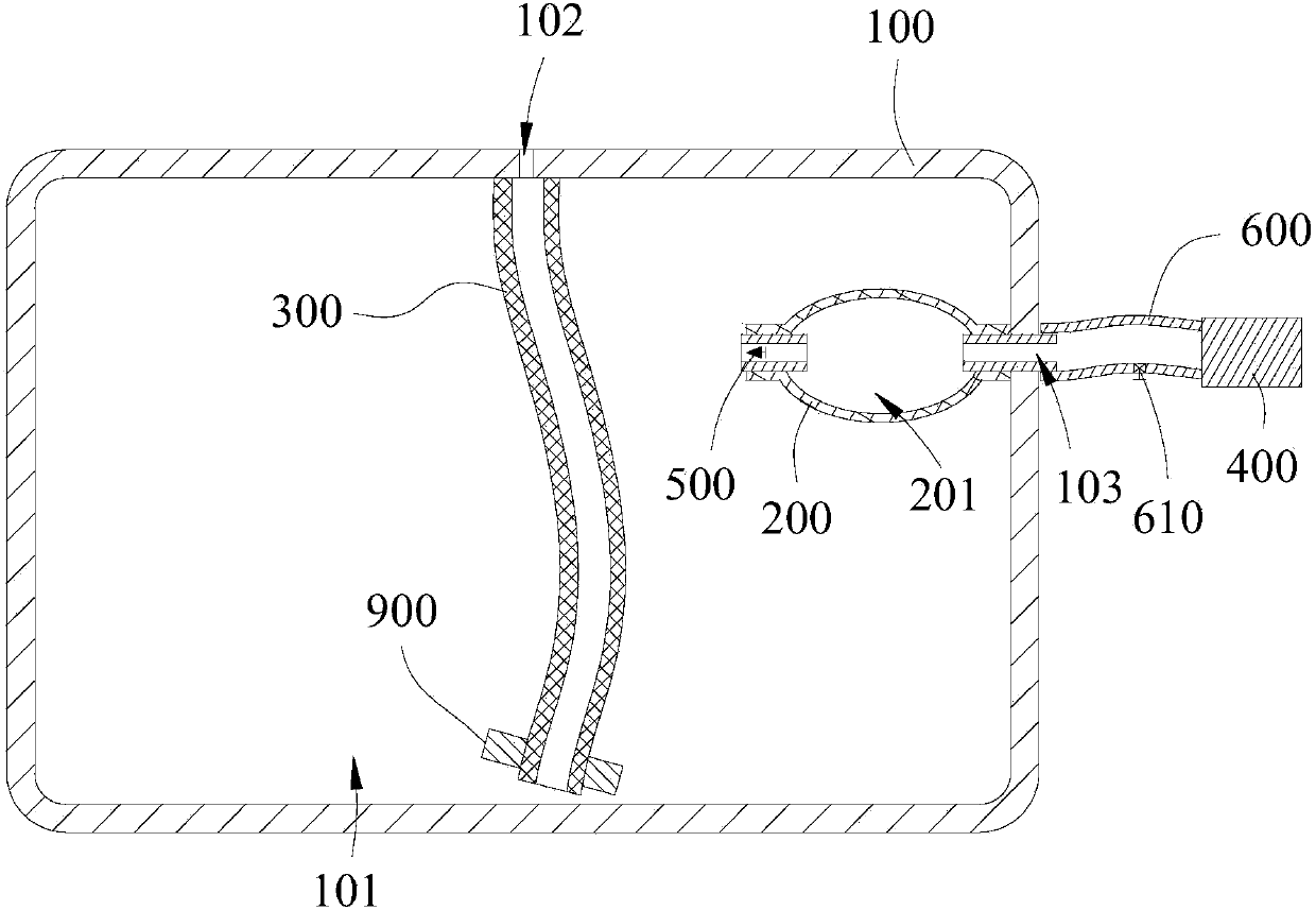
[0027] see figure 1 , the embodiment of the present invention provides a feed assembly, including a feed container 100 , an air bag 200 , a first connecting pipe 300 and an air pump 400 . In a specific application, the feeding component can be set in the roller, directly supply material to the roller, and then brush through the roller, or it can be set between two rollers, directly supply material to the surface to be brushed, and then pass through Apply with two rollers.

[0028] The storage container 100 has a container cavity 101 for storing paint, the size and shape of the storage container 100 and the container cavity 101 can be adjusted according to the needs of use, and the storage container 100 can be made of metal material or plastic material . The material storage container 100 is provided with a material outlet 102 and an air guide hole 103 on the wall of the container cavity 101 , wherein the material outlet 102 is mainly used for overflowing the paint stored in ...

Embodiment 2

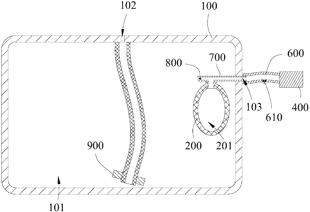
[0040] see figure 2 The difference between the second embodiment and the first embodiment is that the feeding assembly includes an air duct 700 and a second one-way valve 800 disposed in the air duct 700, and the second one-way valve 800 is used to restrict the flow of fluid from the container cavity 101 Into the airway tube 700, the airway tube 700 is provided with a through hole (not marked in the figure) on the tube wall between the second one-way valve 800 and the air guide hole 103, the air bag 200 is connected to the airway tube 700, and the bag cavity 201 passes through the The hole communicates with the air guide hole 103, wherein the air bag 200 is connected to the storage container 100 through the air guide tube 700, and the air bag 200 indirectly isolates the communication between the container cavity 101 and the air guide hole 103 through the air guide tube 700 and the second one-way valve 800. Based on this structural design, when the air pump 400 inflates the ai...

Embodiment 3

[0042] The present invention also proposes a brushing device, which includes a discharge assembly. For the specific structure of the discharge assembly, refer to the first or second embodiment above. The technical solution, therefore, also has all the beneficial effects brought by the technical solution of the above-mentioned embodiment 1 or 2, and will not repeat them one by one here.


PUM


Abstract

The invention discloses a feeding assembly and a coating device. The feeding assembly comprises a storing container (100), an air bag (200), a first connecting pipe (300) and an air pressure pump (400). The storing container (100) is provided with a container cavity (101) used for storing coating, and the container wall of the storing container (100) is provided with a discharging opening (102) and an air guiding hole (103) which both communicate with the container cavity (101). The air bag (200) is made of a flexible material, arranged in the container cavity (101), used for blocking communicating of the container cavity (101) and the air guiding hole (103), and provided with a bag cavity (201) used for storing air. The air guiding hole (103) communicates with the bag cavity (201), and the first connecting pipe (300) is arranged in the container cavity (101) and is in butt joint with the discharging opening (102). The air pressure pump (400) is used for conducting inflation/air exhaust on the bag cavity (201) through the air guiding hole (103). When the feeding assembly needs to stop feeding, the situation of continuous overflowing of the coating cannot occur.

Description

technical field [0001] The invention belongs to the field of paint application, in particular to a feeding assembly and a paint device. Background technique [0002] The feeding component can use the driving force of the air pump to inflate the material. When the feeding needs to be stopped, if only the air pump operation is stopped, the feeding will not stop immediately due to the existence of air pressure, and continuous overflow will occur. If the air pump reversely sucks, it will cause the paint to be adsorbed to the air pump, causing damage to the air pump. Contents of the invention [0003] The purpose of the present invention is to overcome the above-mentioned deficiencies in the prior art, and to provide a discharge assembly, which aims to solve the problem that when the feeding needs to be stopped, if only the operation of the pneumatic pump is stopped, the feeding will not stop immediately and continue In the case of overflow, if the air pump is reversely sucked...

Claims


Application Information

Patent Timeline
Patent Type & Authority Applications(China)
IPC IPC(8): B05C11/10
CPCB05C11/10
Inventor 梁涛
Owner 梁涛
Why Eureka
Try Eureka