Integrated Dehumidification Method and System Combining Boundary Layer Control with Mainstream Disturbance Enhanced Heat Exchange

a dehumidification method and integrated technology, applied in the field of dehumidification and drying, can solve the problems of change in the features of process materials, failure of the corresponding process system, corrosion and malfunction of instruments and parts, etc., to facilitate the flow of fluid, prevent secondary reabsorption of condensate, and enhance the efficiency of air and fluid separation

Inactive Publication Date: 2017-03-09
WANG XIAOHUA
View PDF5 Cites 7 Cited by
  • Summary
  • Abstract
  • Description
  • Claims
  • Application Information

AI Technical Summary

Benefits of technology

[0034]The screen mesh employs the surface tension effect in two ways, the first is the grid mesh size and the second is the distance between the mesh grid and the vane wall surface. In this way, it avoids the need for a big drain directly impacting the condensing field of cold wall surface and facilitates the flow of fluid to the container under the influence of gravity to prevent secondary reabsorption of the condensate. The distance between meshes and vane wall surface depends on the size of flow channel.
[0035]The advantages of the integral heat exchange enhancement system with cold & heat exchange, boundary layer control and mainstream disturbance are: full use of the characteristics of semiconductor transferred heat that overcomes the contradiction of double energy consumption in the traditional drying process. The processing system consists of efficient cooling and dehumidification as well as heat preservation through efficient cooling and dehumidification, from the perspective of flow control and heat transfer enhancement, this provides an innovative method of combining the inertial separation and multi-stage condensation. At the same time as improving the condensation process, it greatly enhances the air and fluid separation efficiency and causes the air condensing in the process of cooling to have lower absolute humidity at the same energy consumption. In the process of heat conservation, the method of boundary layer disturbance is adopted which increases the heat transfer efficiency and ensures that there is no overheating during the processing stage. And at the same time, the temperature of outlet air is highly uniform and conserved heat can be used for drying and storage.

Problems solved by technology

Quick dehumidification of humid air or other process gases is an important issue associated with daily life and with numerous industrial applications.
In the industrial field, the existence of humid air and condensate may directly result in corrosion and malfunction of instruments and parts, or even failure of the corresponding process system.
Meanwhile, humidity will inevitably lead to a change in the features of process materials with adverse effects on production.
However, as this technique adopts the Carnot cycle, the refrigeration agent eventually has an adverse impact on the environment.
Also, despite the high COP, coupling process systems comprising multiple machines inevitably result in excessive consumption of electrical energy.
This type of dehumidification system is also inappropriate for application at adverse ambient temperature (extremely high or low), and is not easy to maintain.
Due to these problems of environmental impact and extremely high energy consumption, its application will be subject to more and more stringent control.
The drying agent may release large quantities of heat during absorption of vapor.
To maintain a great absorption capacity, it is necessary to cool the drying agent during absorption, which inevitably results in increased energy consumption.
And the rotation of the reel results in great noise.
The higher the absorption capacity of the drying agent on the reel is, the higher the energy consumption during regeneration will be, and the higher temperature the regeneration process will require.
Due to the high latent heat produced by evaporation, dehumidification has become one of the main energy consumption parts of the air conditioning system, accounting for 20-40% of the total energy consumption of the air conditioning system.
However, the thermoelectric condensation dehumidification technology has the limits in that the boundary layer blocks the cold and heat transfer, and the mainstream flow cannot be efficiently heated or cooled, thus limiting the heat transfer and dehumidification capacity.
In addition, as the flow speed is progressively slower as it gets closer to the wall, this creates an environment for unclean fluid deposition on the surface of the vane.
This impedes the heat transfer.
This impedes the heat exchange of the integrated fluid with that clinging at the boundary and the overall heat transfer efficiency is reduced.
Therefore, for each single bulge, the flow or vortex created is minimal, and the flow disturbance very limited.
In order to reach the goal of flow disturbance, many such bulges are needed but still does not effectively transfer the energy at the boundary into mainstream, failing to correct the problem of mainstream short flow.
With a traditional cooling and dehumidification method, after the moisture is eliminated, the gas temperature might drop too much to satisfy users' requirements on temperature.
And the traditional way also results in energy waste for reheating of the gas, generally equaling to cool the consumed energy.
This doubles the waste of energy.
This is irrational and in urgent need of solution.

Method used


Image

  • Integrated Dehumidification Method and System Combining Boundary Layer Control with Mainstream Disturbance Enhanced Heat Exchange
  • Integrated Dehumidification Method and System Combining Boundary Layer Control with Mainstream Disturbance Enhanced Heat Exchange
  • Integrated Dehumidification Method and System Combining Boundary Layer Control with Mainstream Disturbance Enhanced Heat Exchange

Examples


embodiment 1

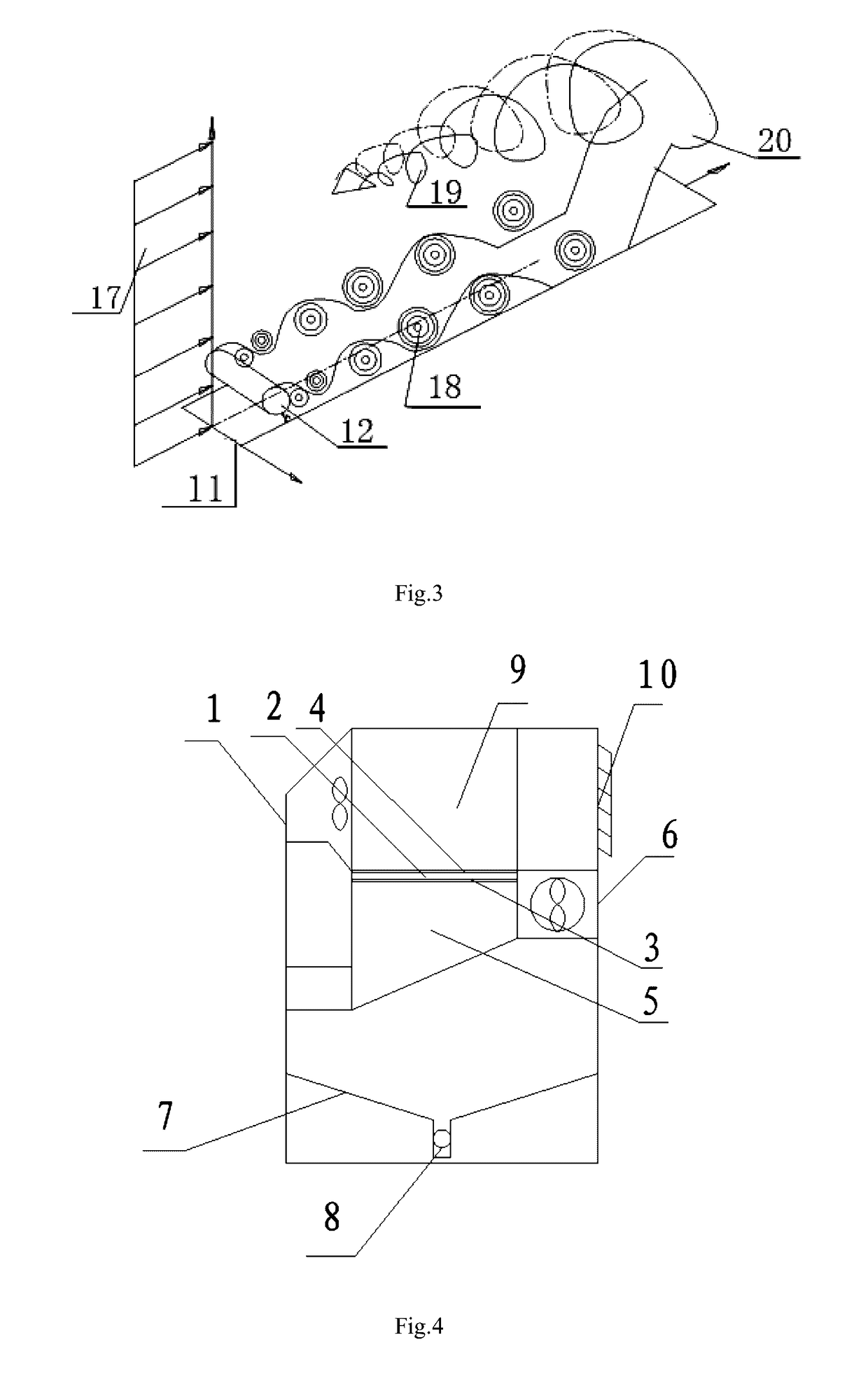
[0049]The integrated dehumidification system combines boundary layer control with mainstream disturbance enhanced heat exchange is shown in FIG. 4, FIG. 5, FIG. 6 and FIG. 8.

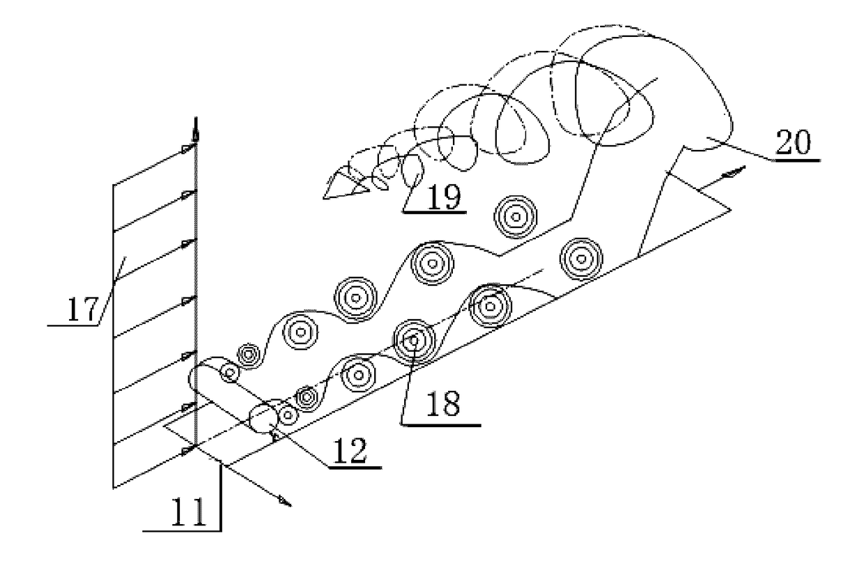
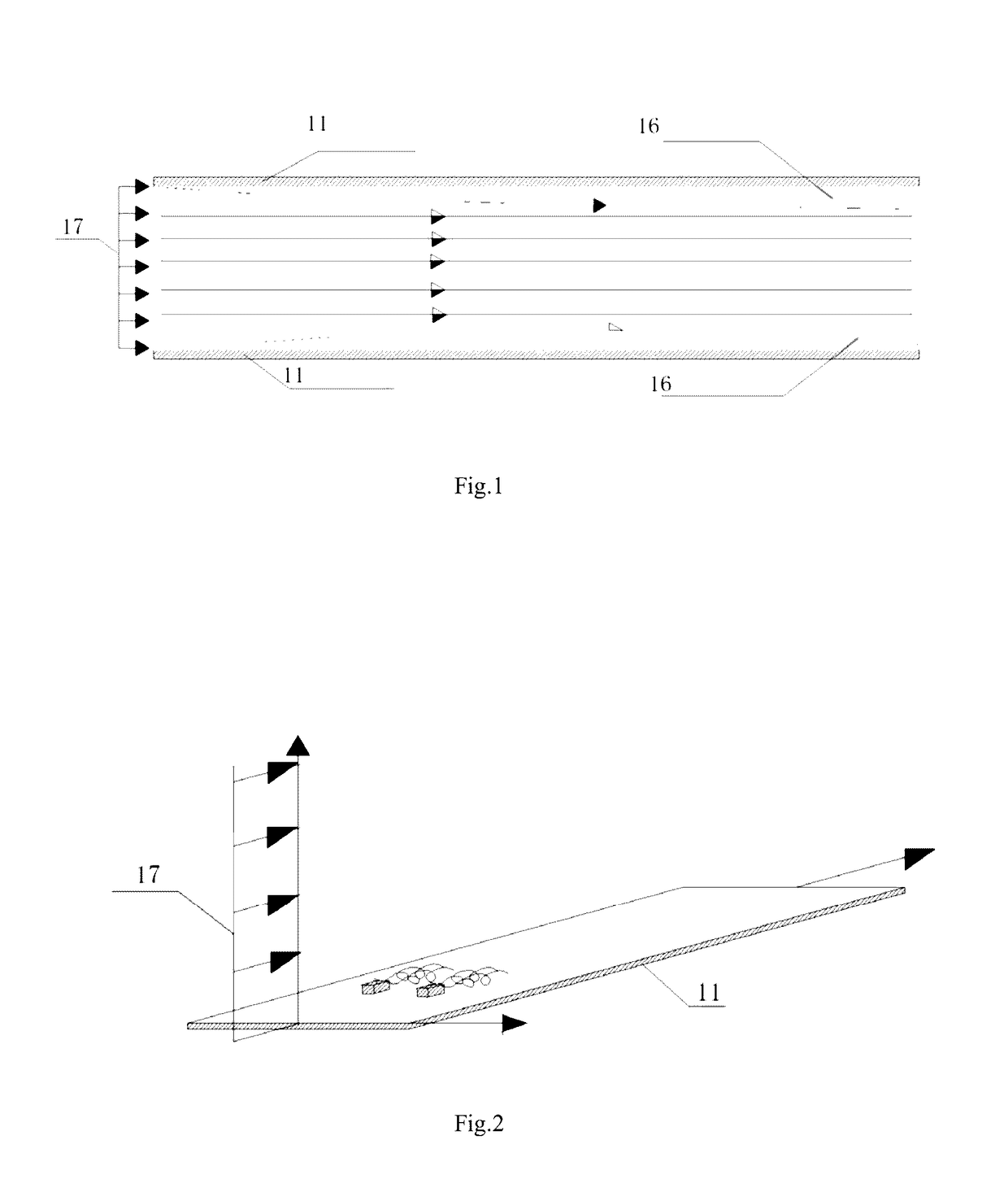
[0050]The system comprises an insulating case 1; a semiconductor thermoelectric device 2 in the insulating case 1, consisting of a cold end 3 and a hot end 4; a first vane assembly on a refrigerating terminal 5 connected below to the cold end 3, an upstream side of the first vane assembly is connected with an air inlet; a catchment trough 7 arranged below the first vane assembly, a drain 8 provided below the catchment trough 7; a second vane assembly on a heating terminal 9 above the hot end 4; the first vane assembly comprising at least two vanes 11 arranged longitudinally, each vane of the first vane assembly is provided multiple boundary layer flow control devices 12 longitudinally arranged adjacent to the wall surfaces of the vane respectively, each vane is a heat conductive hollow pipe structure; the second...

embodiment 2

[0051]The integrated dehumidification system combines boundary layer control with mainstream disturbance enhanced heat exchange is shown in FIG. 4, FIG. 7, FIG. 8 and FIG. 9.

[0052]The system comprises an insulating case 1; a semiconductor thermoelectric device 2 in the insulating case 1, consisting of a cold end 3 and a hot end 4; a first vane assembly on a refrigerating terminal 5 connected below to the cold end 3, an upstream side of the first vane assembly is connected with an air inlet; a catchment trough 7 arranged below the first vane assembly, a drain 8 provided below the catchment trough 7; a second vane assembly on a heating terminal 9 above the hot end 4; the first vane assembly comprising at least two vanes 11 arranged longitudinally, each vane of the first vane assembly is provided multiple boundary layer flow control devices 12 longitudinally arranged adjacent to the wall surfaces of the vane respectively, each vane is a heat conductive hollow pipe structure; the second...

embodiment 3

[0053]Specific configurations are stated as follows relevant to different industrial applications of this invention:

[0054]Domestic dehumidification: Domestic dehumidification mainly involves the storage and quick drying of articles in rainy seasons (hanging articles on the heating terminal); furthermore, it is also highly suitable to provide high-quality air at home. With regard to the wet and cold regions in the Yangtze River basin, this invention can supply separate heating and dehumidification to enhance the users environment while ensuring low energy consumption. When compared with various conventional heating approaches, it will inevitably improve air treatment efficiency owing to its characteristics of separate heating and dehumidification.

[0055]Industrial dehumidification: In view of industrial dehumidification, efficient separation with aerosol has a promising prospect. Conventional dehumidification is normally achieved by means of inertia separation, intercepted separation ...


PUM


Abstract

An integrated dehumidification method that combines boundary layer control with mainstream disturbance enhanced heat exchange comprises heat transfer enhancement units; within each unit, a periodic vortex is formed along a extending direction of the flow channel by setting a boundary layer flow control device adjacent to a boundary layer, thus realizing cleaning of the cold and hot side walls, as a result it destroys the boundary layer blocking heat transfer, and helps to rapidly transfer a cold and heat energy generated on the cold and hot side walls to a flow mainstream channel; a mainstream disturbance device is set on the flow mainstream channel to form an axial vortex at the back of the device to cooperate with a stream emanating from the boundary layer, thus rapidly transferring the cold and heat energy from the boundary layer to a whole field to form an even temperature field.

Description

CROSS REFERENCE TO RELATED PATENT APPLICATION[0001]This application is a continuation in part application (CIP) of the U.S. Ser. No. 14 / 112,758 filed Oct. 18, 2013, which is a national stage of PCT / CN2012 / 070727 filed Jan. 28, 2012 claiming the priority of CN201110197093.8 filed Jul. 14, 2011.FIELD OF THE INVENTION[0002]This invention involves dehumidification and drying, especially a heat transfer enhancement method / system with cold & heat exchange, boundary layer control and mainstream disturbance.BACKGROUND OF THE INVENTION[0003]Quick dehumidification of humid air or other process gases is an important issue associated with daily life and with numerous industrial applications.[0004]Due to the increased public demands for the quality of air, food and medicines humidity control in the production and living environments has become increasingly important. In the industrial field, the existence of humid air and condensate may directly result in corrosion and malfunction of instruments...

Claims


Application Information

Patent Timeline
Patent Type & Authority Applications(United States)
IPC IPC(8): F24F3/14B01D53/26F24F13/22F24F5/00F24F13/08
CPCF24F3/14F24F5/0042F24F13/08F24F2003/1446B01D53/265F24F2221/46F24F13/222F24F3/1405
Inventor WANG, XIAOHUA
Owner WANG XIAOHUA
Why Eureka
Try Eureka