Mattress

一种床垫、位移的技术,应用在床垫领域

Inactive Publication Date: 2018-04-17
SUMITOMO RIKO CO LTD
View PDF13 Cites 0 Cited by
  • Summary
  • Abstract
  • Description
  • Claims
  • Application Information

AI Technical Summary

Problems solved by technology

[0004] However, it is hard to say that enough research has been done on the flexing action of mattresses

Method used


Image

  • Mattress
  • Mattress
  • Mattress

Examples


Embodiment Construction

[0073] Hereinafter, embodiments of the present invention will be described with reference to the drawings.

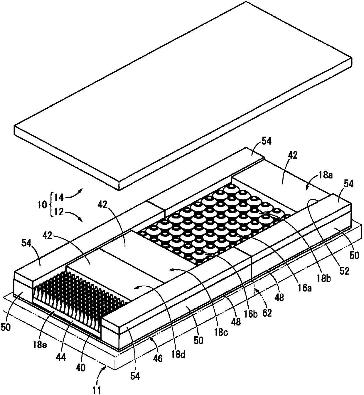
[0074] exist figure 1 In , the mattress 10 which is 1st Embodiment of this invention is shown. The mattress 10 is configured by combining a mattress main body 12 laid on a bed 11 and a cover 14 covering the upper surface of the mattress main body 12 . In addition, in figure 1 In FIG. 2 , the mattress main body 12 and the cover body 14 are shown in a state separated up and down for easy identification.

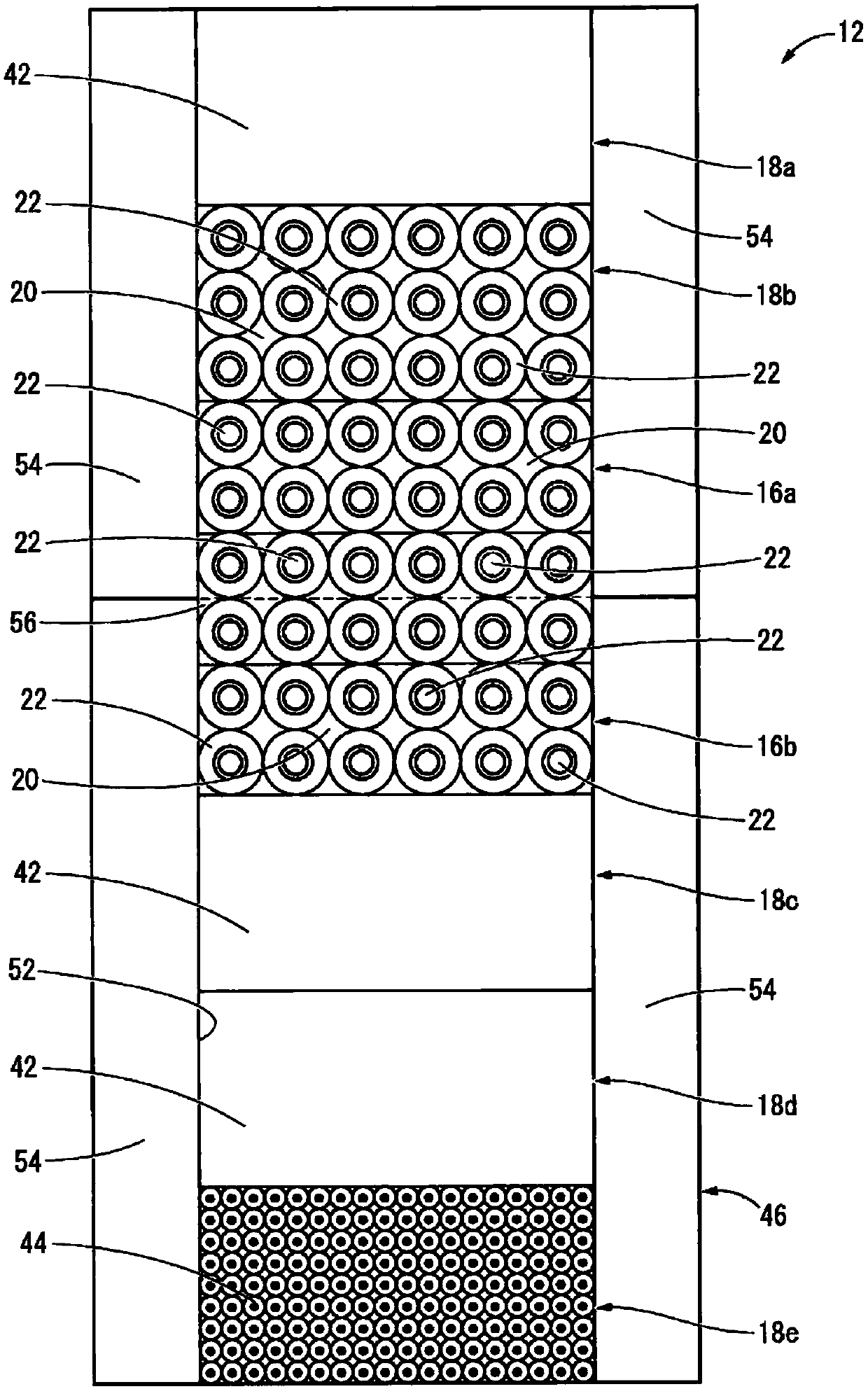
[0075] More specifically, as figure 1 , figure 2 As shown, the mattress body 12 includes two cell units 16a, 16b and five segmented units 18a, 18b, 18c, 18d, 18e.

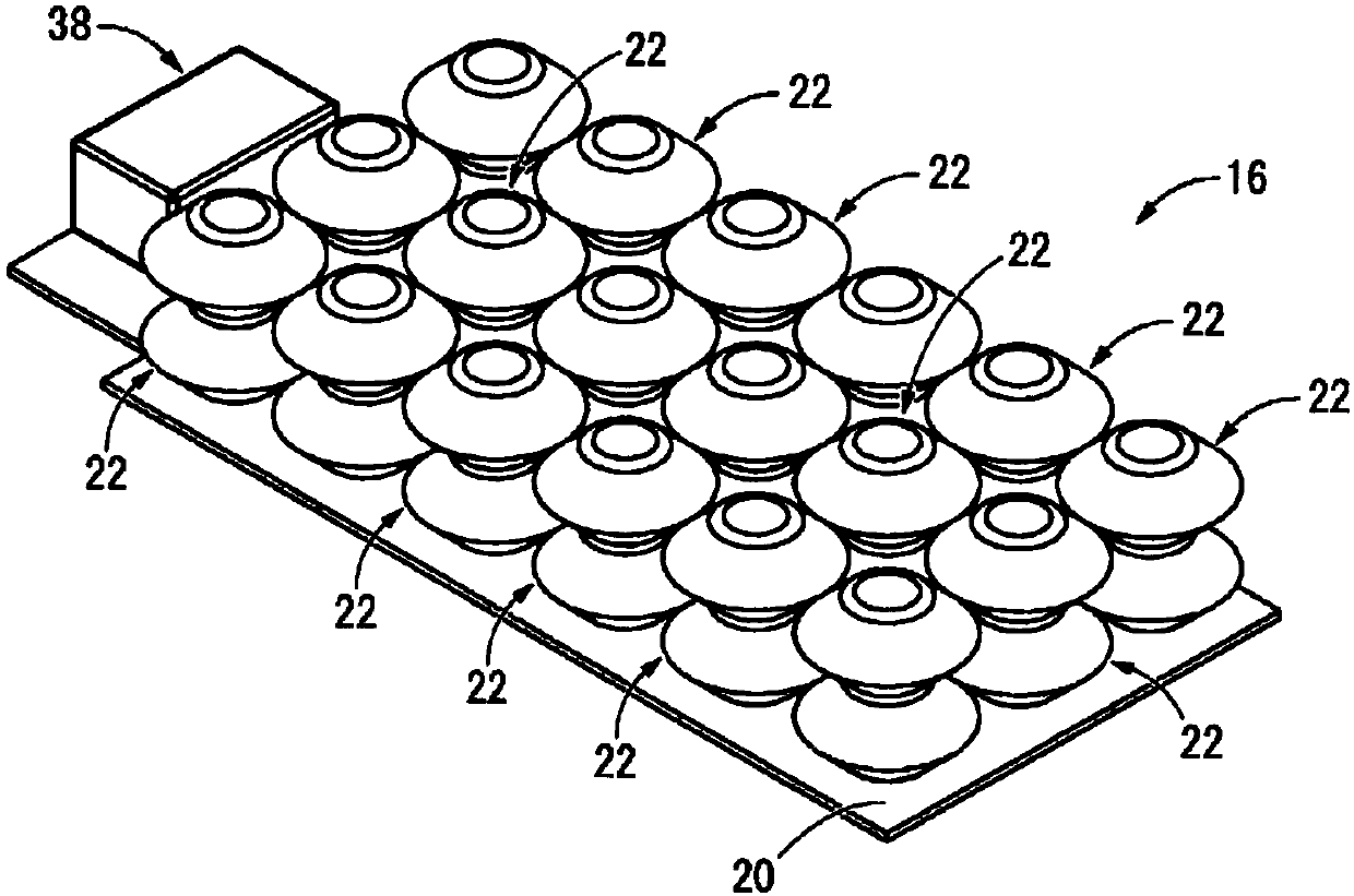
[0076] Such as Figure 3 ~ Figure 5 As shown, the cell unit 16 has a structure in which a plurality of cells 22 are attached to a base 20 formed of plate-shaped or sheet-shaped polyurethane foam or the like. The cell unit 16 of this embodiment has 18 cells 22 on the base 20, and the cells 22 are ar...


PUM


Abstract

The purpose of the present invention is to provide a mattress having a new structure capable of achieving the stabilization of cell behavior and excellent comfort while achieving a back-raising operation. Provided is a mattress 10 having a structure in which a plurality of cells 22 are arranged, which are provided with a fluid chamber on the upper surface of a base body 20 for supporting a human body, wherein the base body 20 is divided at a waist bend section 62 set at a portion in the bed length direction, cell units 16a, 16b having a structure in which the cells 22 are arranged on each of the divided base body 20 are arranged adjacently across the waist bend section 62, and a connecting body 56 is provided, is arranged astride the cell units 16a, 16b, which are adjacent across the waistbend section 62, and is supported by the cells 22 of said cell units 16a, 16b.

Description

technical field [0001] The present invention relates to a mattress suitable for nursing care beds and the like. Background technique [0002] Conventionally, mattresses have been proposed which have a structure in which a plurality of cells are provided on a base supporting a human body for the purpose of preventing decubitus ulcers in the elderly and disabled persons who have difficulty turning over on their own. The above-mentioned mattress is disclosed in, for example, Japanese Unexamined Patent Application Publication No. 2013-27531 (Patent Document 1). The mattress adjusts the pressure (body pressure) acting on the user's body by adjusting the supply and discharge of the fluid in the cell. Therefore, it is expected to prevent bedsores and the like by dispersing body pressure. [0003] In addition, in nursing care beds, etc., there are beds with a back raising function that makes the user's upper body stand up when eating, etc., and a mattress suitable for such a bed wi...

Claims


Application Information

Patent Timeline
Patent Type & Authority Applications(China)
IPC IPC(8): A47C27/10A47C17/165
CPCA61G7/015A61G7/05707A61G7/05769A47C27/10A47C17/165
Inventor 中村康宽山田博早川知范御崎晶嗣
Owner SUMITOMO RIKO CO LTD
Why Eureka
Try Eureka