Snakelike surgical instrument
A surgical instrument, snake-shaped technology, applied in the field of medical devices, can solve the problems of complex control of snake-shaped surgical instruments
- Summary
- Abstract
- Description
- Claims
- Application Information
AI Technical Summary
Problems solved by technology
Method used
Image
Examples
Embodiment 1
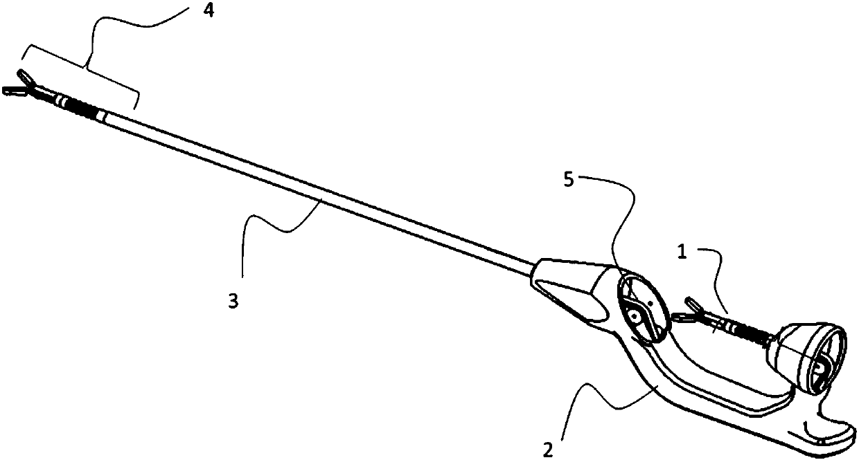
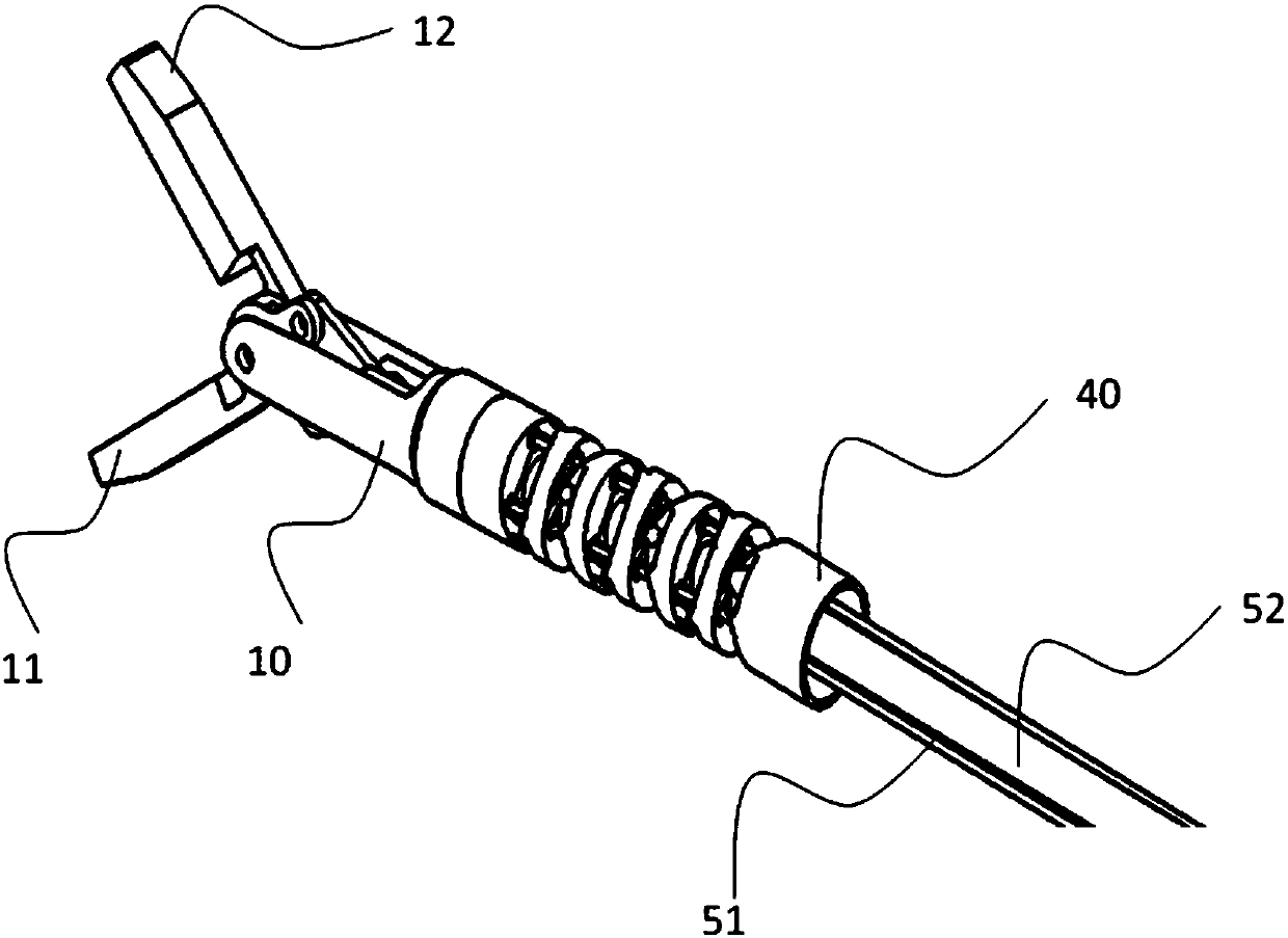
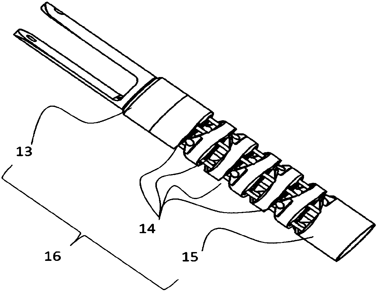
[0053] like figure 1 As shown, the serpentine surgical instrument includes a manipulation structure 1 , a hand-held structure 2 , a connection structure 3 , an end instrument 4 and a transmission device 5 . The manipulation structure 1 is installed on one end of the hand-held structure 2 . One end of the connection structure 3 is connected to the hand-held structure 2, and the other end is connected to the terminal instrument 4, and the transmission device 5 is configured to make the terminal instrument 4 swing in the same direction under the drive of the control structure 1, that is, the control structure 1 is controlled by the transmission device 5 Movement of the end instrument 4 . The free end of the manipulation structure 1 extends in the same direction as the free end of the terminal instrument 4 . Wherein, both the handheld structure 2 and the connecting structure 3 have cavity structures inside. The transmission device 5 can be arranged in the above-mentioned cavity...
Embodiment 2
[0064] The type of end effector is not limited. When the end effector is an instrument with relative rotation, such as scissors, electric hooks, and clamps, the end instrument 4 of the hand-held serpentine device needs to have opening and closing degrees of freedom in addition to two rotational degrees of freedom.
[0065] like Figure 8 , Figure 13 and Figure 14 As shown, the end instrument 4 has two tool flap structures, namely a left tool flap 42 and a right tool flap 43 . Both the left tool flap 42 and the right tool flap 43 are rotatably connected to the tool support seat 41 . For example, the tool support seat 41 has a radial shaft hole structure, one end of the opening and closing flap 42 on the left side is rotationally connected with the tool support seat 41 through the radial shaft hole structure, and the other end is a free end. One end of the opening and closing flap 43 on the right side is rotationally connected with the tool support seat 41 through a radial...
Embodiment 3
[0085] like Figure 20-21 In the illustrated embodiment, a rotational connection can also be realized between the gripping structure 10 in the manipulation structure 1 and the first serpentine base 13, so that the gripping structure 10 has the ability to rotate (rotate) around the axis of the gripping structure 10. Rotational degree of freedom R3'. Correspondingly, the tool support base 41 can rotate relative to the serpentine structure 40 , and the tool support base 41 has a rotational degree of freedom R3 of rotating around the axis of the tool support base 41 (autorotation) relative to the serpentine structure 40 .
[0086] The transmission device 5 also includes a second flexible structure (not shown), one end of the second flexible structure is connected to the gripping structure 10 , and the other end is connected to the tool support seat 41 in the terminal instrument 4 . The gripping structure 10 drives the second flexible structure to rotate, and then drives the tool ...
PUM
 Abstract
Description
Claims
Application Information
 - R&D
- Intellectual Property
- Life Sciences
- Materials
- Tech Scout
- Unparalleled Data Quality
- Higher Quality Content
- 60% Fewer Hallucinations
Browse by: Latest US Patents, China's latest patents, Technical Efficacy Thesaurus, Application Domain, Technology Topic, Popular Technical Reports.
© 2025 PatSnap. All rights reserved.Legal|Privacy policy|Modern Slavery Act Transparency Statement|Sitemap|About US| Contact US: help@patsnap.com


