
Gripper structure and industrial robot gripper

A technology of industrial robots and abutment parts, which is applied in the direction of manipulators, manufacturing tools, chucks, etc., can solve the problems of waste of resources, poor stability of pneumatic finger support, and different hole sizes

Pending Publication Date: 2018-04-20
GUANGZHOU SEYOUNTH AUTOMATION TECH CO LTD
View PDF0 Cites 5 Cited by
  • Summary
  • Abstract
  • Description
  • Claims
  • Application Information

AI Technical Summary

Problems solved by technology

[0002] With the continuous advancement of science and technology, the structure of mechanical grippers is widely used in assembly line operations. When the traditional mechanical gripper grabs materials, it often grabs the outer wall of the material. This kind of grabbing method is easy to pollute the material. The head supports the inner hole of the material to grasp the material. However, in actual production, the shape of the inner hole of the material is various and the size of the hole is different. It is difficult for the traditional pneumatic finger to make a Adaptive adjustment, so when supporting the inner hole of the material, the stability of the pneumatic finger support is poor, so it is necessary to equip corresponding grippers for different materials, which wastes resources

Method used


Image

  • Gripper structure and industrial robot gripper
  • Gripper structure and industrial robot gripper
  • Gripper structure and industrial robot gripper

Examples


Embodiment Construction

[0026] In order to make the above objects, features and advantages of the present invention more comprehensible, specific implementations of the present invention will be described in detail below in conjunction with the accompanying drawings. In the following description, numerous specific details are set forth in order to provide a thorough understanding of the present invention. However, the present invention can be implemented in many other ways different from those described here, and those skilled in the art can make similar improvements without departing from the connotation of the present invention, so the present invention is not limited by the specific implementations disclosed below.

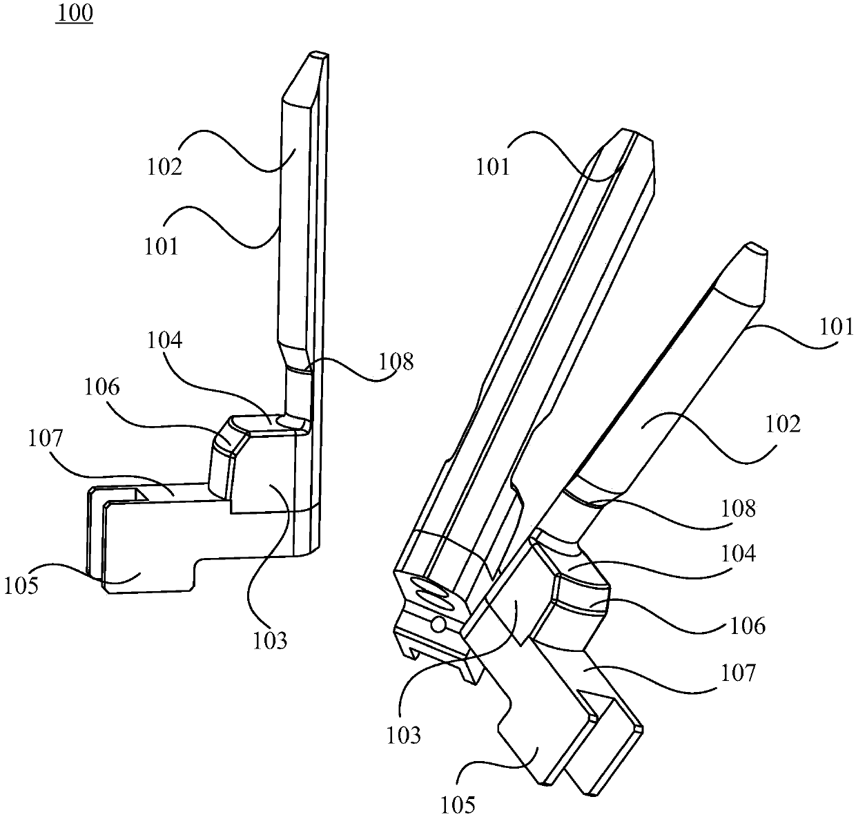
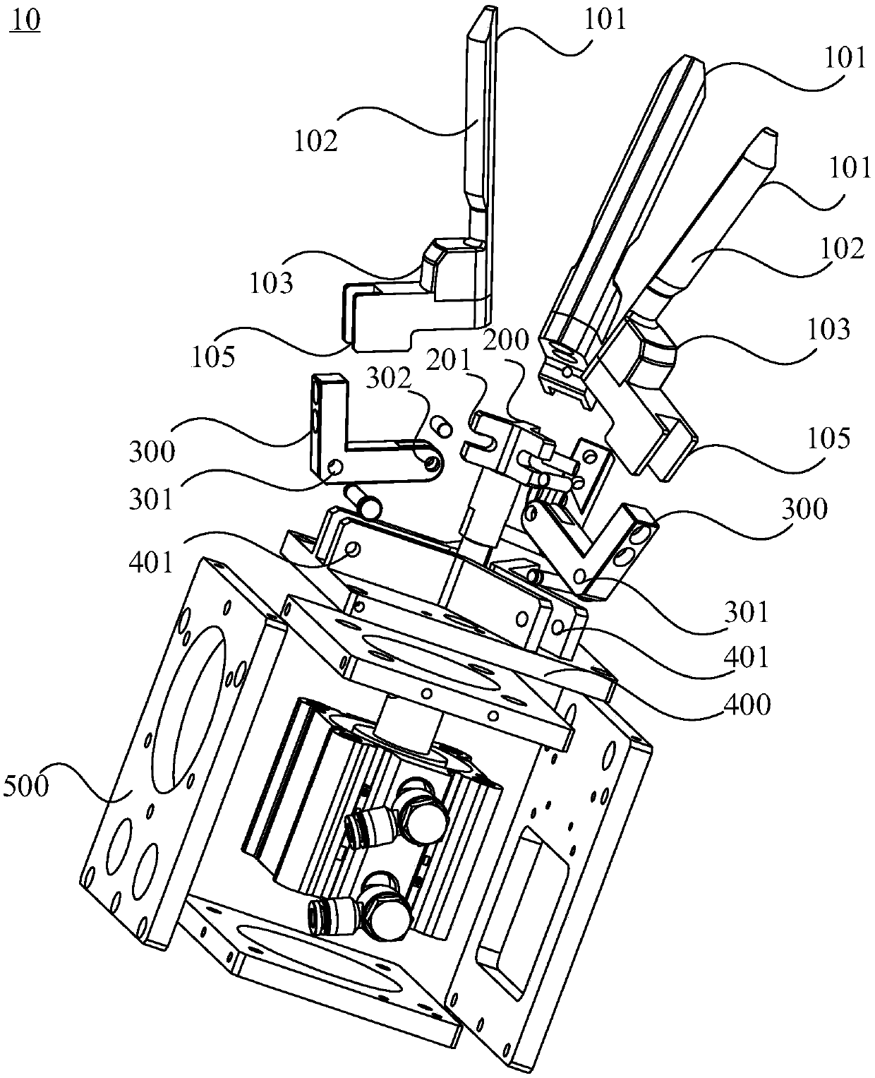
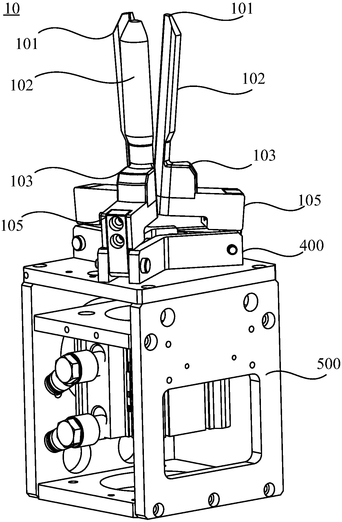
[0027] Such as figure 1 As shown, a gripper structure is disclosed in one embodiment, including: a mounting seat 400, the mounting seat 400 is provided with at least two mounting parts, and all the mounting parts are arranged at intervals along the same first circumference; and a grip...


PUM


Abstract

The invention discloses a gripper structure and an industrial robot gripper. The gripper structure comprises a mounting seat and a gripping head assembly, wherein the mounting seat comprises two mounting parts which are arranged at intervals along the same first circumference; the gripping head assembly comprises at least two gripping heads; all the gripping heads are arranged at intervals along the same second circumference; each gripping head is provided with a connector and a gripping head body; one end of each connector is rotatably connected with the corresponding mounting part while theother end of each connector and one end of the corresponding gripping head body are fixed, so that the other end of each gripping head body can be away from a center line of the second circumference to stretch or can be close to the center line of the second circumference to retract; the outer side of each gripping head body is provided with a first abutting part and a second abutting part which are arranged at intervals along the two ends of the gripping head body; all the first abutting parts are matched with one another to form a first abutting structure; all the second abutting parts are matched with one another to form a second abutting structure; and therefore, during use, the first abutting structure and the second abutting structure are abutted against an inner hole wall of a material so as to achieve the purpose of multi-point abutting against the inner hole wall of the material.

Description

technical field [0001] The invention relates to the field of mechanical manufacturing, in particular to a gripper structure and an industrial robot gripper. Background technique [0002] With the continuous advancement of science and technology, the structure of mechanical grippers is widely used in assembly line operations. When the traditional mechanical gripper grabs materials, it often grabs the outer wall of the material. This kind of grabbing method is easy to pollute the material. The head supports the inner hole of the material to grasp the material. However, in actual production, the shape of the inner hole of the material is various and the size of the hole is different. It is difficult for the traditional pneumatic finger to make a Adaptive adjustment, so when supporting the inner hole of the material, the stability of the pneumatic finger support is poor, so it is necessary to equip corresponding grippers for different materials, which wastes resources. Content...

Claims


Application Information

Patent Timeline
IPC IPC(8): B25J15/00B25J15/02B25J15/10
CPCB25J15/0047B25J15/0206B25J15/10
Inventor 岑均豪洪巍陆坤明
Owner GUANGZHOU SEYOUNTH AUTOMATION TECH CO LTD
Learn More