
Offshore wind power generator with self-protection function

A technology for wind turbines and protection functions, applied in wind turbines, wind turbine combinations, wind power generation, etc., can solve problems such as economic losses, prone to overturning, and large torsional loads.

Active Publication Date: 2018-04-20
龚羽佳
View PDF5 Cites 1 Cited by
  • Summary
  • Abstract
  • Description
  • Claims
  • Application Information

AI Technical Summary

Problems solved by technology

However, due to the harsh and complex operating environment of the ocean, offshore wind turbines are subjected to the impact and influence of various extreme loads such as ocean, current, wind, and waves, resulting in excessive torsional loads and excessive yaw motions. This will very likely lead to the overturning of offshore wind turbines, affecting the reliability, safety and normal use of offshore wind turbines, resulting in huge economic losses
Most of the existing offshore wind turbines are connected to the seabed by cables. The purpose of preventing overturning is achieved through this rigid connection protection structure. The cables are usually made of metal, and because the torsional loads on offshore wind turbines and cables are large, The yaw movement is violent, and the reliability of the work is low. After being eroded by time, it is very likely to cause corrosion damage or fatigue fracture, which will cause the offshore wind turbine to capsize in the absence of restraining force.
In addition, the large number of blades of wind turbines results in an excessively large frontal area, which results in excessive resistance and is more prone to overturning

Method used


Image

  • Offshore wind power generator with self-protection function

Examples


Embodiment Construction

[0025] In order to make the object, technical solution and advantages of the present invention clearer, the present invention will be further described in detail below in conjunction with the accompanying drawings and specific implementation methods. It should be understood that the specific embodiments described here are only used to explain the present invention, and do not limit the protection scope of the present invention.

[0026] It should be noted that when an element is referred to as being “fixed on”, “disposed on” or “installed on” another element, it may be directly on the other element or there may be an intervening element. When an element is considered to be "connected" to another element, it may be directly connected to the other element or there may be an intervening element at the same time; the specific way that one element is fixedly connected to another element can be realized through existing technologies, and will not be discussed here. To repeat it agai...


PUM


Abstract

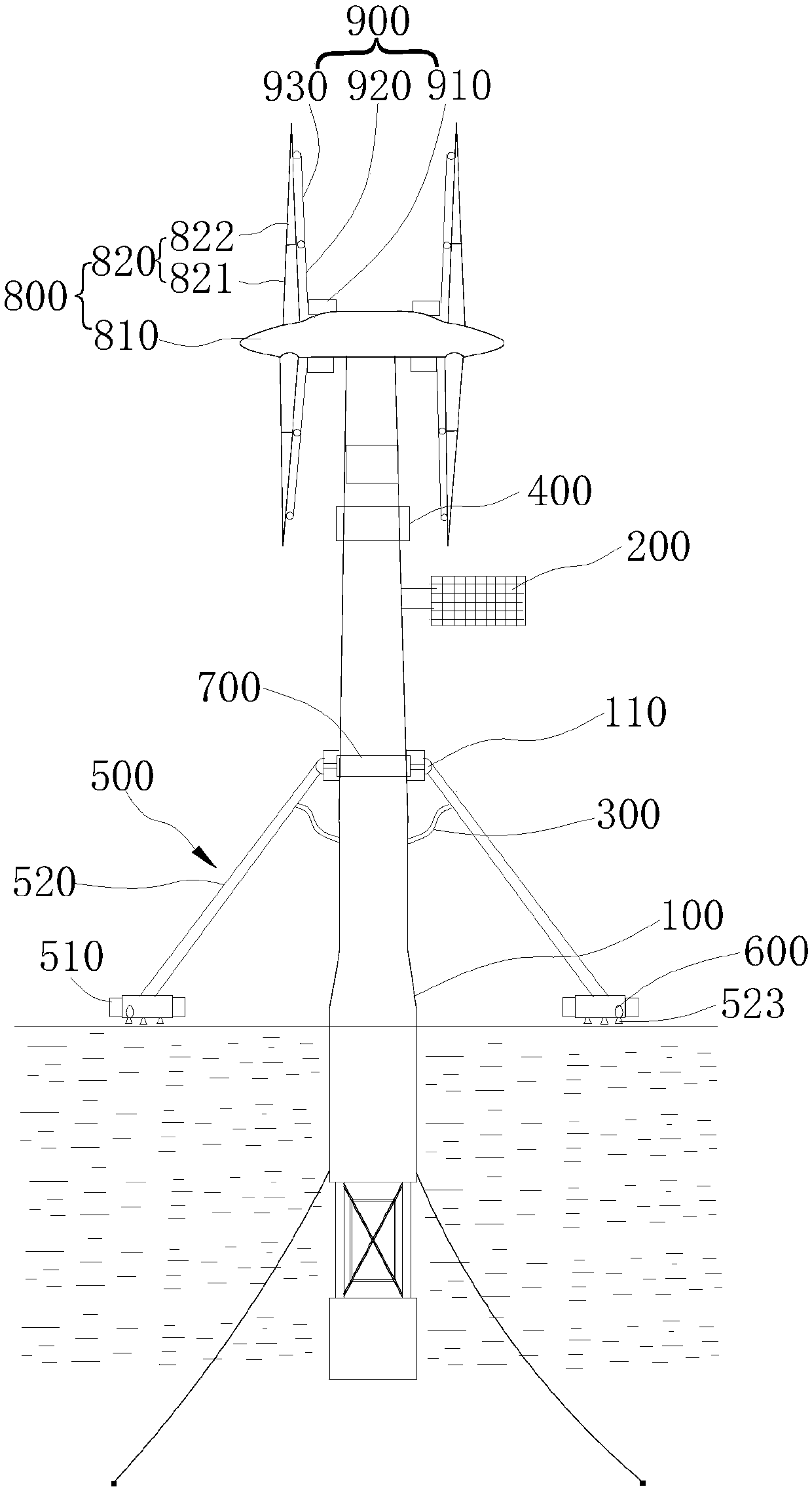
The invention discloses an offshore wind power generator with a self-protection function. The generator comprises a floating platform, a wind turbine, a water supply hose and a self-balancing mechanism, wherein the self-balancing mechanism comprises at least three self-balancing components; the self-balancing component comprises a floating body, a water flow driving part and a balance arm providedwith a water jet flow channel; a water inlet of the water jet flow channel is communicated with the other end of the water supply hose, the balance arm comprises a connecting end and a floating end;the connecting end is connected with a connecting lug, the floating body is arranged on the floating end, and the water flow driving part is communicated with the water jet flow channel and electrically connected with the control device; in this way, the balance arm can obtain counter-acting force generated by washing force and can form lateral support for the fan foundation, so that automatic posture correction can be realized on the basis of the fan, the balance state of the wind-driven generator can be adjusted in a self-adaptive mode on the premise of avoiding the use of the cable, and thesituation that the wind-driven generator is stressed is avoided, so that when the wind driven generator is impacted and affected by various limit loads such as ocean, flow, wind, waves and the like,the wind driven generator can be prevented from being overturned.

Description

technical field [0001] The invention relates to the technical field of offshore wind power generators, in particular to an offshore wind power generator with a self-protection function. Background technique [0002] With the rapid development of science and technology, and the country's continuous advocacy of the development and application of new energy and new technologies, many non-polluting, low energy consumption, and low-cost energy sources are gradually widely used, such as wind energy. At present, wind power generators use the most wind energy, and offshore wind power generators are the most widely used. However, due to the harsh and complex operating environment of the ocean, offshore wind turbines are impacted and affected by various extreme loads such as ocean, current, wind, and waves, resulting in excessive torsional loads and excessive yaw motions. This will very likely cause the offshore wind turbine to capsize, affecting the reliability, safety and normal us...

Claims


Application Information

Patent Timeline
IPC IPC(8): F03D9/25F03D13/25F03D80/00H02S10/12
CPCF03D9/007F03D9/25F03D13/25F03D80/00H02S10/12Y02E10/50Y02E10/72Y02E10/727
Inventor 龚羽佳
Owner 龚羽佳
Learn More