Illumination shadowless lamp used for neurological surgery operation and with real-time image transmission function

A real-time imaging and neurosurgery technology, applied in the field of medical devices, can solve the problems of lighting shadowless lamps, patient injury, and small camera range, and achieve the effect of solving medical disputes.

Inactive Publication Date: 2018-04-20
周双荷
View PDF2 Cites 3 Cited by
  • Summary
  • Abstract
  • Description
  • Claims
  • Application Information

AI Technical Summary

Problems solved by technology

[0008] In order to solve the above-mentioned technical problems, the present invention provides a lighting shadowless lamp with real-time image transmission function for neurosurgery, to solve the problem that the camera set by the existing lighting shadowless lamp has a small shooting range and cannot record the operation in all directions. Every detail in the process will lead to subsequent medical disputes, because the details have not been recorded, and effective evidence cannot be provided, resulting in medical disputes that cannot be effectively resolved; the existing lighting shadowless lamps are fixed by a support and fixing bracket On the top of the operating table, after a long period of use, the connecting nuts on the supporting and fixing brackets may also become loose. If they are not found and replaced or tightened in time, it is very easy to turn the lighting shadowless lamp during the operation. The pulling pressure will easily cause the nut to fall off directly, causing the shadowless lighting lamp to fall or fall, causing serious injury to the patient on the operating table, and causing a major safety accident.

Method used


Image

  • Illumination shadowless lamp used for neurological surgery operation and with real-time image transmission function
  • Illumination shadowless lamp used for neurological surgery operation and with real-time image transmission function
  • Illumination shadowless lamp used for neurological surgery operation and with real-time image transmission function

Examples


Embodiment

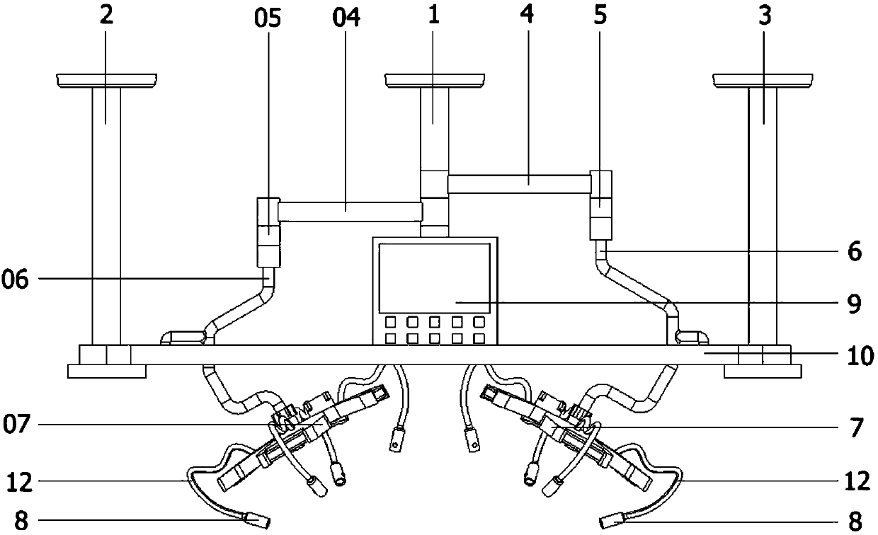
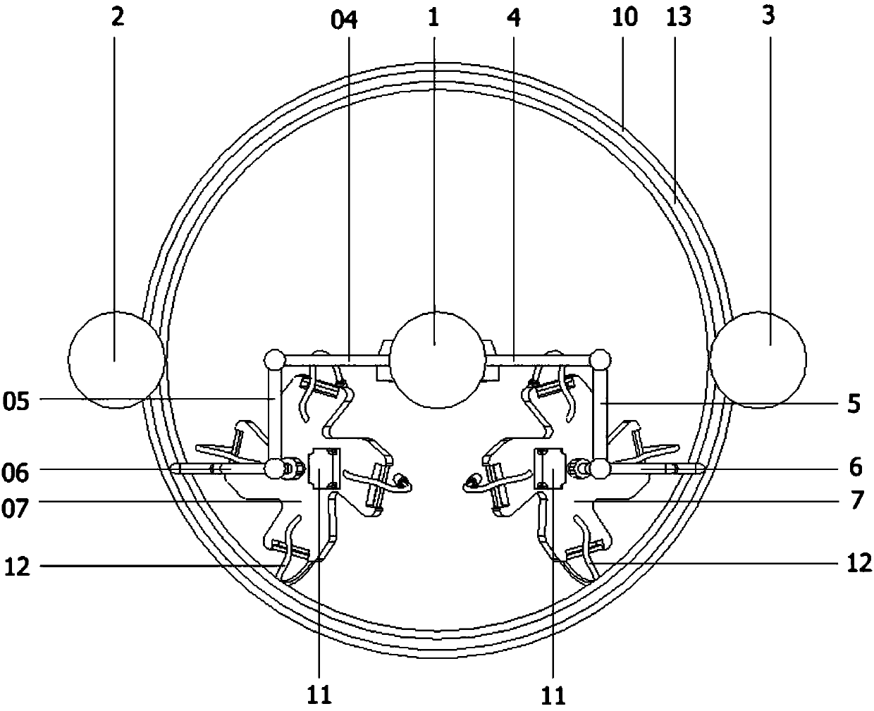
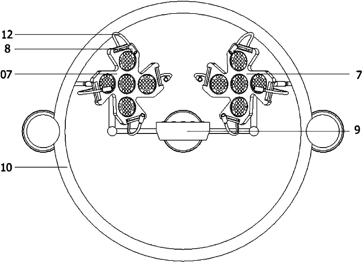
[0033] as attached figure 1 to attach Figure 9 Shown:

[0034] The present invention provides a lighting shadowless lamp with real-time image transmission function for neurosurgery, including a main fixing bracket 1, a left side auxiliary support fixing bracket 2, a right side auxiliary support fixing bracket 3, and a right first connecting arm 4 , the second connecting arm on the right side 5, the third connecting arm on the right side 6, the main body of the shadowless lamp on the right side 7, the micro camera main body 8, the display 9, the annular ring 10, the terminal box 11, the metal hose 12, the annular chute 13, Metal universal spherical connector 14, sliding support rod 15, ball 16, left first connecting arm 04, left second connecting arm 05, left third connecting arm 06 and left shadowless lamp main body 07; the main The fixed bracket 1 is fixed on the top of the operating table by bolts; the bottom end of the main fixed bracket 1 is pivotally connected to the f...


PUM


Abstract

The invention provides a lighting shadowless lamp with real-time image transmission function for neurosurgery, which includes a main fixing bracket and a main body of the left shadowless lamp; the main fixing bracket is fixed above the operating table by bolts; the right second The three connecting arms and the third connecting arm on the left side are connected to one of the sliding support rods, and the two sliding supporting rods are connected to the top of the annular ring by the ball slidingly connected by the bottom. In the said annular chute opened. Through the setting of the eight groups of micro-camera main bodies, it is beneficial to adjust the eight groups of micro-camera main bodies to different positions during the operation, so as to record every detail in the operation process in an all-round way, which is beneficial to follow-up if medical disputes occur. , can provide effective evidence and effectively resolve medical disputes.

Description

technical field [0001] The invention belongs to the technical field of medical devices, and in particular relates to a lighting shadowless lamp with real-time image transmission function for neurosurgery. Background technique [0002] Surgical camera system is an essential tool for medical treatment, teaching, scientific research and telemedicine. The existing medical shadowless illuminating lamp is composed of an illuminating bulb and a light frame fixed to the illuminating lamp in terms of structural design. Its shortcomings: the shadowless lighting only has the function of lighting, but not the function of on-site camera, so there is no camera data during the operation, which is not convenient for future academic exchanges and teaching; secondly, when doctors have medical disputes, doctors and patients Both parties are unable to provide real evidence, causing mutual distrust between doctors and patients, and it is difficult to distinguish the authenticity of the evidence...

Claims


Application Information

Patent Timeline
IPC IPC(8): F21S8/00F21V17/12F21V19/00F21V23/00F21V33/00F21W131/205
CPCF21S8/00F21V17/12F21V19/00F21V23/003F21V33/0052F21W2131/205
Inventor 周双荷李华想杨海龙
Owner 周双荷
Why Eureka
Try Eureka