Multifunctional keyboard
A multi-functional, keyboard technology, applied in the direction of instrumentation, electrical digital data processing, user/computer interaction input/output, etc., can solve problems such as easy to absorb dust, difficult to clean dust, dirty keyboard surface, etc., to achieve a comfortable working environment , keep clean, and inhibit the keyboard from accumulating dust
- Summary
- Abstract
- Description
- Claims
- Application Information
AI Technical Summary
Problems solved by technology
Method used
Image

Examples
Embodiment 1
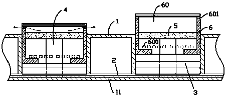
[0015] exist figure 1 In the first embodiment shown, the multifunctional keyboard includes a base shell 1, a support plate 11 is formed at the bottom of the base shell 1, and a circuit film 2 is provided on the support plate 11; each switch node of the circuit film 2 There is a button hole on the top, and the bottom of the button hole is provided with an elastic body 3 that is in contact with the switch node of the circuit film; The conductive rubber body in point contact, when the elastic body 3 presses the switch node, the switch node is conducted by the conductive rubber body; this structure is a conventional structure of a traditional keyboard.
[0016] A base column 4 extending upward along the axis of the key hole is fixed on the support plate 11, and a slide plug 5 is fixed on the upper end of the base column 4, and the slide plug 5 extends into a keycap matching the key hole. 6 inside the sliding cavity 60; the lower end of the keycap 6 is in contact with the elastic ...
Embodiment 2
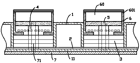
[0020] for figure 2 The second embodiment shown is different from the first embodiment in that the axis of the base column 4 is provided with a longitudinal tunnel through the base column 4 and the base shell 1; a bottom plate is also provided under the base shell 1 7. The upper surface of the bottom plate 7 is distributed with plug posts 71 corresponding to each of the longitudinal channels; after each plug post 71 on the bottom plate 7 is completely inserted into each of the longitudinal channels, the lower end of each longitudinal channel is completely blocked, and the bottom plate 7 forms a support for the base shell 1; after each plug post 71 on the bottom plate is completely pulled out of each of the longitudinal holes, the bottom plate 7 is completely separated from the base shell 1, and the When the base shell 1 is placed horizontally on the desktop, there is a gap between each of the longitudinal holes and the desktop. According to Embodiment 2, when the wall hole 6...
Embodiment 3
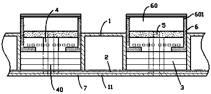
[0022] exist image 3 In the third embodiment shown, different from the first embodiment, the axis of the base column 4 is provided with a longitudinal channel 40 that runs through the base column 4 and the base shell 1, and the longitudinal channel 40 is located in the base shell 1. Bottom holes are formed on the bottom plane of the base shell 1; the bottom of the base shell 1 is provided with adjustable feet (not shown in the figure, which can be composed of adjusting nuts) that can continuously adjust the supporting height; when the adjustable feet are adjusted to the lowest supporting height, the The bottom plane of the base shell 1 is completely attached to the desktop, and the bottom holes on the bottom plane are sealed by the desktop; when the adjustable feet are adjusted to the highest support height, there is a gap between the bottom plane of the base shell 1 and the desktop. 10mm-15mm interval. Thus, by adjusting the support height of the adjustable feet, the distan...
PUM
 Abstract
Description
Claims
Application Information