Garbage bag extractor

Inactive Publication Date: 2012-03-08
JONES SCOTT M
View PDF12 Cites 5 Cited by
  • Summary
  • Abstract
  • Description
  • Claims
  • Application Information

AI Technical Summary

Benefits of technology

[0004]There are countless types of trash and garbage bags available in different sizes and shapes with different closure meth

Problems solved by technology

In spite of the advantages inherent in using garbage or trash bags, removal of the bag from the can pose problems, particularly for those with limited physi

Method used


Image

  • Garbage bag extractor
  • Garbage bag extractor
  • Garbage bag extractor

Examples


Embodiment Construction

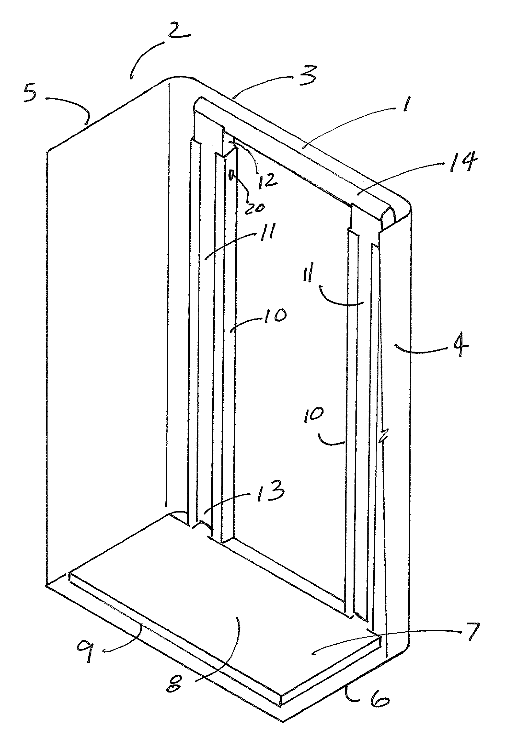
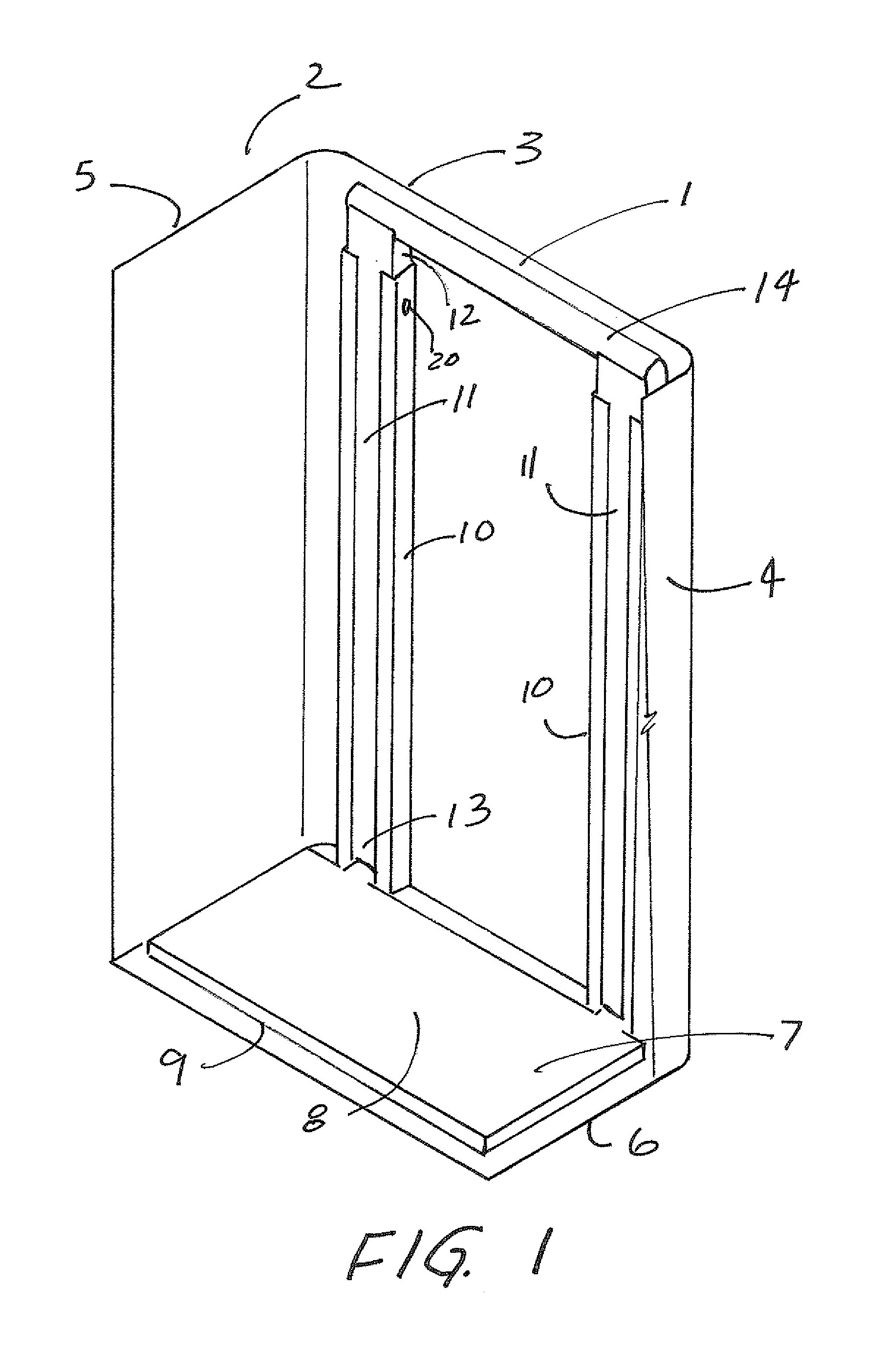
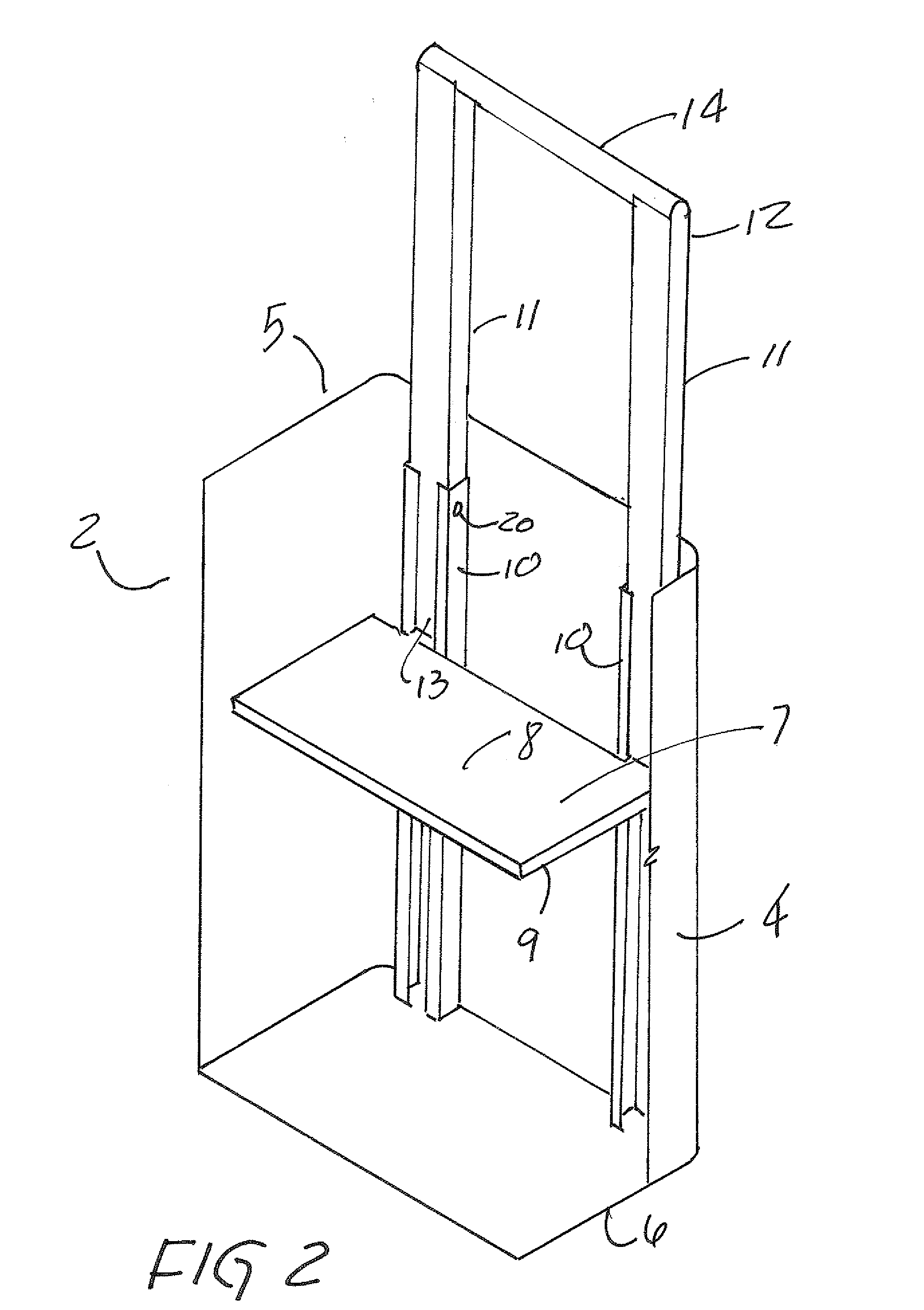
[0011]FIG. 1 depicts a trash can 2 with a manual embodiment of the inventive garbage bag extractor 1 in place. The front and right side 4 of the trash can 2 have been cut away for clarity. It is understood that a garbage bag would be placed in the trash can 2 to receive waste and garbage from above in the normal fashion. As shown, the garbage bag extractor 1 has a lifting platform 7 fitted to the cross sectional shape of the trash can 2 with a top side 8 and a bottom side 9, the lifting platform 7 resting in the bottom 6 of the trash can 2. At the top 8 of the lifting platform 7 are attached the bottom ends 13 of vertical lifting arms 11 that ride in vertical slide rails 10 attached to the rear interior side 3 of the trash can 2. The top ends 12 of the lifting arms 11 are attached to a pull handle 14. Also shown is at least one venting hole 20 meant to break the natural vacuum created when the lifting platform 7 is raised. In this embodiment, air would be drawn the slide rails 10 th...


PUM


Abstract

A garbage bag extractor for removal of a garbage bag from a trash can where the extractor has a flat lifting platform fitted to the cross sectional shape of a trash can, vertical lifting arms, slide rails with a pull handle for manually raising the lifting platform in the trash can, supplemented with a rack and pinion drive with a mechanically driven pinion gear turning on a vertical gear rack riding in a rack guide.

Description

[0001]This application claims priority from U.S. Provisional application Ser. No. 61 / 402,755 (“the '755 application”) filed Sep. 4, 2010. The '755 application is incorporated herein by reference.BACKGROUND OF THE INVENTION[0002]The present invention generally relates to devices for removal of garbage bags from trash cans and trash receptacles.SUMMARY OF THE INVENTION[0003]In the typical household and virtually everywhere that trash cans are used to collect discarded waste materials of any kind, plastic bags of some type are used to line the trash cans. When full, the bags are removed from the trash can and discarded for pick up and disposal under some waste management scheme.[0004]There are countless types of trash and garbage bags available in different sizes and shapes with different closure methods, but most are meant to be used in a trash can to ease in the removal of waste and to keep the trash can relatively clean.[0005]In spite of the advantages inherent in using garbage or t...

Claims


Application Information

Patent Timeline
IPC IPC(8): B65D35/14
CPCB65F1/068
Inventor JONES, SCOTT M.
Owner JONES SCOTT M
Why Eureka
Try Eureka