Silo with breakage lowering devices with L-shaped flow baffles and grain loading method
A technology of crushing device and spoiler, applied in the directions of transportation and packaging, loading/unloading, etc., can solve the problems of loss, difficulty in production and installation, easy breakage and grading, etc., to improve service life, reduce installation cost, and facilitate high and low positions. Effect
- Summary
- Abstract
- Description
- Claims
- Application Information
AI Technical Summary
Problems solved by technology
Method used
Image
Examples
Embodiment 1
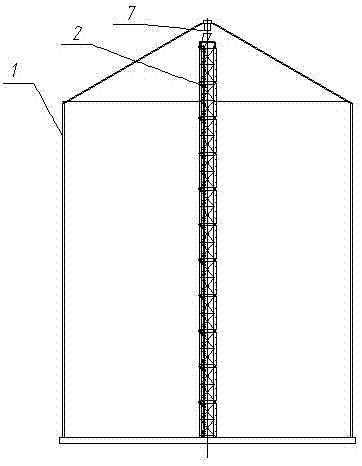
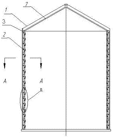
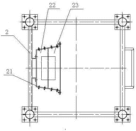
[0032] A silo with a descending crushing device with L rows of baffles, its composition includes: a silo 1, a grain feeding pipe 7 is distributed in the silo, and a group of descending crushing devices 2 are installed in the silo , the upper part of the falling crushing device is the grain inlet 3 corresponding to the grain feeding pipe, the falling crushing device has a trough body 21, and a group of The bluff bodies A22 are arranged in parallel, and a set of bluff bodies B23 are connected to the flanges on both sides of the trough-shaped body. The inclination angle of the bluff bodies A is symmetrical, the bluff bodies B are parallel to each other, and the grain outlet 4 is formed between the bluff bodies B.
Embodiment 2
[0034] According to the silo of the falling crushing device with L rows of baffles described in embodiment 1, there are 1-4 falling crushing devices, there may be a central falling crushing device located in the center of the circle, and the rest are evenly distributed on the circumference, or All mounted on the circumference.
[0035] Each of the falling crushing devices has 3-20 sections, and the length of each section is 1.5-3 meters. There is a socket structure between the sections of the falling crushing device, and the bottom of the previous section is sleeved on the top of the next section, and fixed.
[0036] The section of the bluff body B is L-shaped, Figure 4 or Figure 5 shown.
Embodiment 3
[0038] In the silo of the descending crushing device with L rows of baffles described in Embodiment 1 or 2, the inclination a of the bluff body A and the bluff body B is 31-42°, and the bluff body described after installation The distance L between A is 220-850mm, the distance L1 between the bluff bodies B is 220-850mm; from top to bottom: the distance L2 between the bluff body B and the bluff body A is greater than The distance between the bluff body A and the bluff body B is L3, and the difference between L2 and L3 is 0-400 mm. Generally, it is better to arrange grains at unequal distances.
PUM
 Abstract
Description
Claims
Application Information
 - R&D
- Intellectual Property
- Life Sciences
- Materials
- Tech Scout
- Unparalleled Data Quality
- Higher Quality Content
- 60% Fewer Hallucinations
Browse by: Latest US Patents, China's latest patents, Technical Efficacy Thesaurus, Application Domain, Technology Topic, Popular Technical Reports.
© 2025 PatSnap. All rights reserved.Legal|Privacy policy|Modern Slavery Act Transparency Statement|Sitemap|About US| Contact US: help@patsnap.com


