
Screwing jig

A technology of jig and frame body, applied in the field of jig, can solve the problems of looseness, product assembly requirements, cumbersome and other problems, and achieve the effect of convenient operation

Pending Publication Date: 2018-05-01
SHANGHAI HANGJIA ELECTRONICS TECH
View PDF10 Cites 1 Cited by
  • Summary
  • Abstract
  • Description
  • Claims
  • Application Information

AI Technical Summary

Problems solved by technology

[0003] However, the inventors have found that when the rod-shaped or column-shaped component and the nut are screwed together, since the nut is located inside the housing, in order to avoid the phenomenon of co-rotation of the rod-shaped or column-shaped component or the nut when the column-shaped component rotates , the worker needs to use additional tools such as vise, wrench, etc. to first clamp the nut located in the shell, and then rotate the rod or column parts. The whole process is not only laborious, but also very cumbersome
At the same time, in the process of tightening, since it is generally tightened manually with both hands, the tightening force cannot meet the assembly requirements of the product for a long time, so it often appears loose during use.

Method used


Image

  • Screwing jig
  • Screwing jig
  • Screwing jig

Examples


Embodiment Construction

[0033] In order to make the purpose, technical solutions and advantages of the embodiments of the present invention more clear, various implementation modes of the present invention will be described in detail below in conjunction with the accompanying drawings. However, those of ordinary skill in the art can understand that, in each implementation manner of the present invention, many technical details are provided for readers to better understand the present application. However, even without these technical details and various changes and modifications based on the following implementation modes, the technical solution claimed in this application can also be realized.

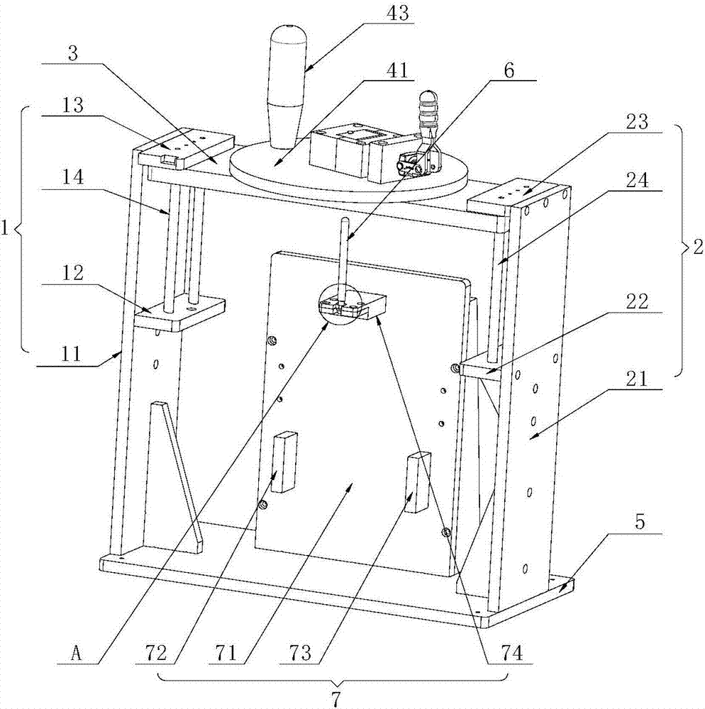
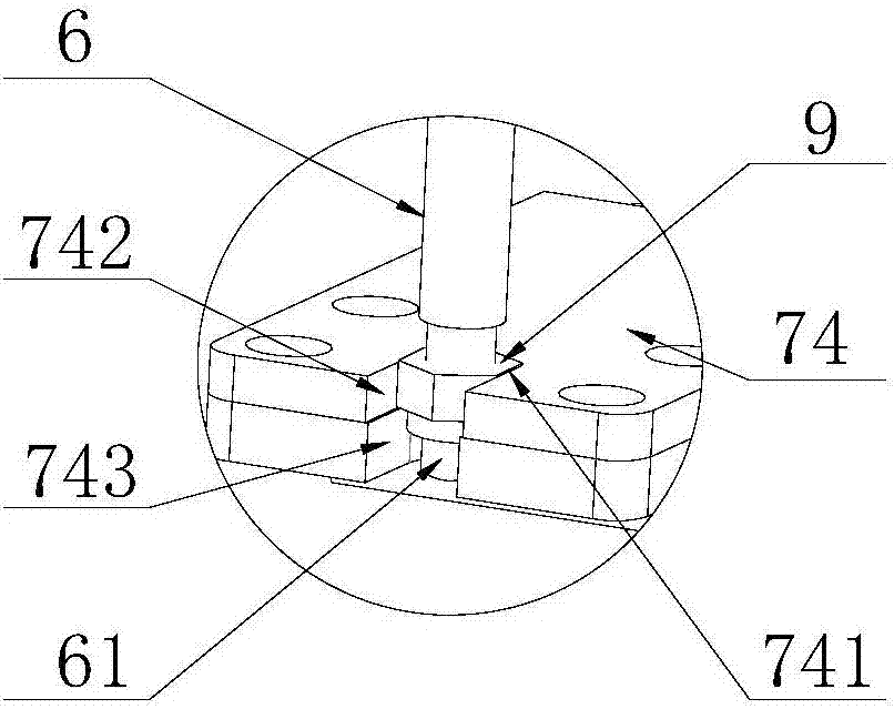
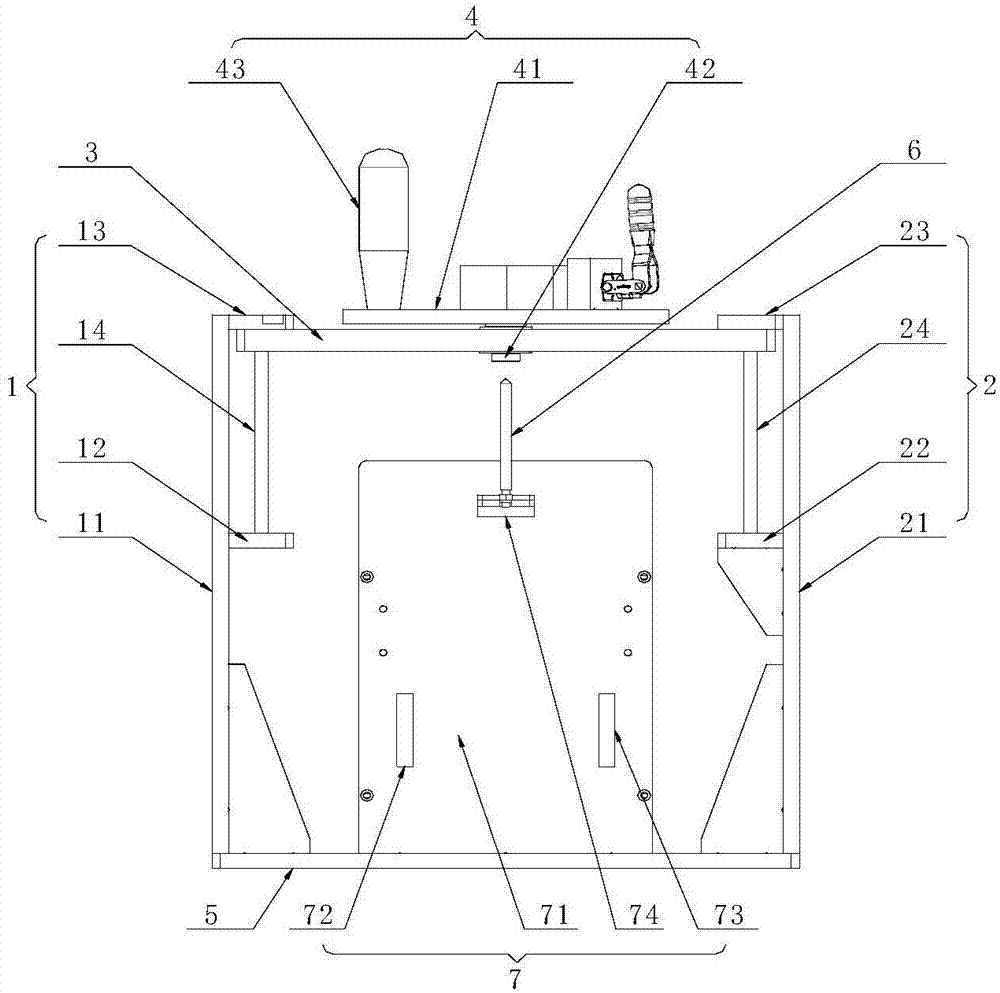
[0034] The first embodiment of the present invention relates to a tightening fixture, such as figure 1 and image 3 As shown, the tightening jig utilizes a nut 9 to screw the rod-shaped or column-shaped component 6 with a stud on the side wall 81 of the housing 8 provided with a through hole 82 . Specific ...


PUM


Abstract

The embodiment of the invention relates to a jig, in particular to a screwing jig. The screwing jig comprises a first frame body, a second frame body, a pressing plate, a rotary disc mechanism and a jig body, wherein the pressing plate is arranged between the first frame body and the second frame body and is used for carrying out linear sliding in the height direction of the first frame body and the height direction of the second frame body, the rotary disc mechanism is arranged on the pressing plate in a rotating mode and is used for clamping a rod-shaped or column-shaped part, and the jig body is arranged between the first frame body and the second frame body and is used for fixing a shell and a nut. Compared with the prior art, the screwing jig has the advantages that a worker can drivethe rod-shaped or column-shaped part to rotate by taking the axis of a double-screw bolt as the center through the rotary disc mechanism so that screwing of the double-screw bolt and the nut can realized, the operation is convenient, meanwhile, the rotating disc mechanism can be driven to gradually descend by pressing the pressing plate downwards, and therefore the phenomenon that the rod-shapedor column-shaped part is separated from the rotary disc mechanism in the screwing process of the rod-shaped or column-shaped part and the nut can be avoided; and in addition, the nut is fixed by the jig body, so that the screwing of the double-screw bolt and the nut can be easily realized, and therefore the actual use requirements can be met.

Description

technical field [0001] The invention relates to a jig, in particular to a tightening jig. Background technique [0002] During the assembly process of the product, it is inevitable that some rod-shaped or cylindrical parts with studs are fixed on the shell of the product through nuts, but during the fixing process, since the nuts are generally fixed inside the shell , while the rod-shaped or column-shaped parts are fixed on the outside of the housing, during assembly, the studs on the rod-shaped or column-shaped parts can be passed through the through holes pre-opened on the housing, and then the stud parts and The screw cap located in the housing is screwed to realize the fixation of the rod-shaped or column-shaped component on the housing. [0003] However, the inventors have found that when the rod-shaped or column-shaped component and the nut are screwed together, since the nut is located inside the housing, in order to avoid the phenomenon of co-rotation of the rod-sha...

Claims


Application Information

Patent Timeline
Patent Type & Authority Applications(China)
IPC IPC(8): B23P19/00B23P19/06
CPCB23P19/00B23P19/06
Inventor 房超靳尔中
Owner SHANGHAI HANGJIA ELECTRONICS TECH
Learn More