
Suspension touch sensing method, suspension touch sensing system and suspension touch electronic device

A floating touch and sensing method technology, applied in the electronic field, can solve problems such as users are not easy to click, icons are automatically opened, etc., so as to avoid false touches and provide accuracy.

Active Publication Date: 2021-04-06
SHENZHEN ROYOLE TECH CO LTD
View PDF4 Cites 1 Cited by
  • Summary
  • Abstract
  • Description
  • Claims
  • Application Information

AI Technical Summary

Problems solved by technology

However, during floating touch, since the finger is far away from the icon, it is not easy for the user to precisely click the desired position. It is possible that the target point of the floating touch is just within the touch hotspot of a certain icon. For example, the user The finger just hovers over the edge of the icon. At this time, a false touch will occur, and the icon will automatically open, instead of expecting the corresponding action

Method used


Image

  • Suspension touch sensing method, suspension touch sensing system and suspension touch electronic device
  • Suspension touch sensing method, suspension touch sensing system and suspension touch electronic device
  • Suspension touch sensing method, suspension touch sensing system and suspension touch electronic device

Examples


Embodiment Construction

[0034] The following will clearly and completely describe the technical solutions in the embodiments of the present invention with reference to the drawings in the embodiments of the present invention.

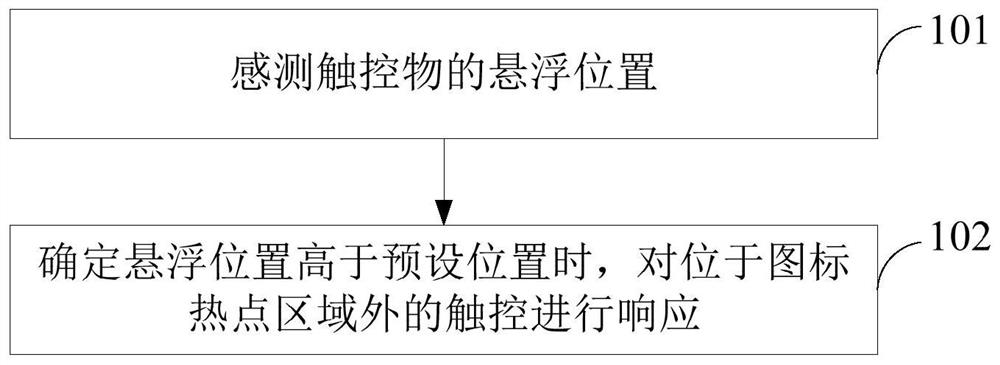
[0035] see figure 1 , the embodiment of the first solution of the present invention provides a floating touch sensing method. The floating touch sensing method is applied to floating touch electronic equipment. Wherein, the floating touch electronic device includes a touch display panel. The touch display panel includes a plurality of icon hotspot areas and non-icon hotspot areas. The floating touch sensing method includes the following steps:

[0036] Step 101 , sensing the floating position of the touch object.

[0037] It should be noted that when the floating touch electronic device is applied, touch operations need to be performed on the touch display panel. That is, the touch object (such as a finger) does not need to directly touch the screen of the touch display p...


PUM


Abstract

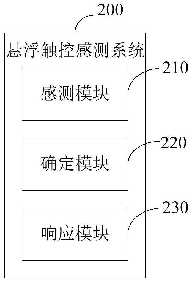
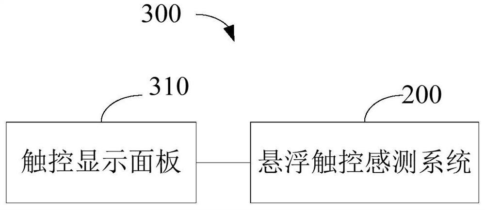
A floating touch sensing method, applied to a floating touch electronic device (300), the floating touch electronic device (300) includes a touch display panel (310), and the touch display panel (310) includes a multi- an icon hotspot area (312) and a non-icon hotspot area (314), the floating touch sensing method includes sensing the floating position of the touch object (101); Touches outside the hotspot area are responded to (102). Therefore, false touches can be avoided by setting the preset position, thereby improving the accuracy of touch control. Also provided are a floating touch sensing system (200) and a floating touch electronic device (300).

Description

technical field [0001] The present invention relates to the field of electronics, in particular to a suspension sensing touch method, a suspension touch sensing system and suspension touch electronic equipment. Background technique [0002] In recent years, the rapid development of microelectronics technology, computer software and hardware technology has laid a foundation for terminal equipment to handle more and more complex tasks. In addition, users themselves have urgent needs for terminals, hoping that terminals will be more powerful, more flexible, and simpler. With the development of terminal technology, the input mode of terminal equipment has gradually changed from the original physical keys to virtual keys, and virtual keys are usually also called soft keys and soft keyboards. However, even so, the terminal's input technology still needs to be improved. For example, the input mode is relatively simple and the user experience is insufficient. Due to the limited s...

Claims


Application Information

Patent Timeline
Patent Type & Authority Patents(China)
IPC IPC(8): G06F3/0481G06F3/0488G06F3/041G06F3/042G06F3/044
CPCG06F3/0412G06F3/0418G06F3/042G06F3/044G06F3/04817G06F3/04883G06F3/041G06F3/0481G06F3/0488G06F3/04186G06F3/04886G06F2203/04101
Inventor 林麒杨松龄杨帆
Owner SHENZHEN ROYOLE TECH CO LTD
Learn More