Adjusting hand wheel structure for sighting telescope with self-locking function
A technology for adjusting handwheels and sights. It is used in aiming devices, weapon accessories, offensive equipment, etc. It can solve the problems of accidentally touching the adjustment nail, affecting the shooting accuracy, and moving, so as to avoid the phenomenon of accidental contact and stabilize the shooting accuracy.
- Summary
- Abstract
- Description
- Claims
- Application Information
AI Technical Summary
Problems solved by technology
Method used
Image
Examples
Embodiment 1
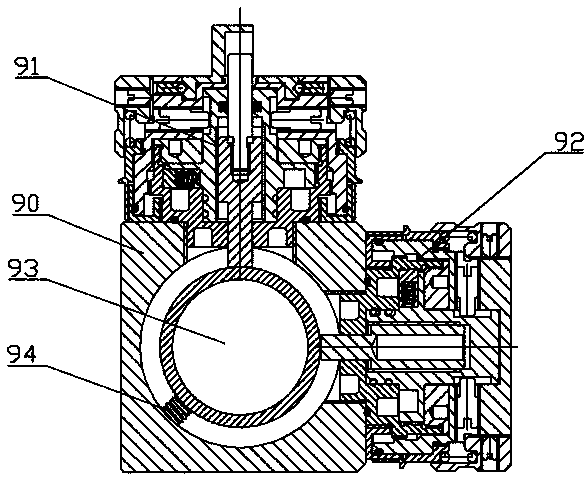
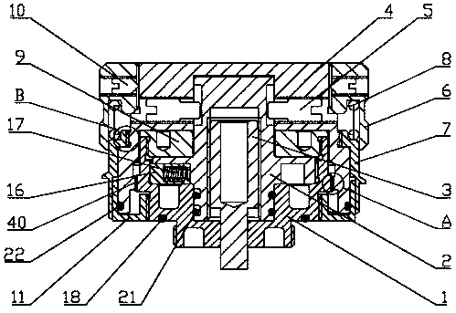
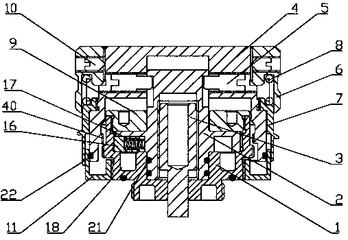
[0035] Such as Figure 2-4As shown, the UP adjustment handwheel structure 91 includes an adjustment nail seat 1 arranged on the scope mirror body, a rotatable adjustment nail 2 arranged in the adjustment nail seat 1, and a rotatable adjustment nail 2 located in the adjustment nail 2. The adjusting nail head 3 adjusted up and down and the adjusting nail cover 4 arranged on the adjusting nail seat 1, the outside of the adjusting nail seat 1 meshes with the inner gear of the adjusting nail cover 4, and the adjusting nail cover 4 The lifting of the A gear can separate or lock the meshing part of the gear A. Under normal conditions, since the outside of the adjusting nail seat 1 is engaged with the inner gear of the adjusting nail cover 4, the adjusting nail cover 4 is locked on the adjusting nail On the seat 1, the adjusting nail head 3 cannot be adjusted at this time. After the adjusting nail cover 4 is lifted, the locking relationship between the adjusting nail cover 4 and the a...
Embodiment 2
[0042] Such as Figure 5-7 As shown, the structure of this embodiment is basically the same as that of Embodiment 1. The difference is that in this embodiment, the circle number reminder function of the scope is also added. Specifically, the top of the adjusting nail head 3 is vertically An adjustment nail indicator shaft 12 is arranged directly, and an adjustment nail indicator sleeve 13 is arranged on the top of the adjustment nail cover 4, and an observation window 130 and a horizontal indicator line 131 located at the observation window 130 are arranged on the adjustment nail indication sleeve 13. , the adjusting nail indicating shaft 12 passes through the adjusting nail 2 and is located in the adjusting nail indicating sleeve 13, the adjusting nail indicating sleeve 13 is rotatably matched with the adjusting nail cover 4, and the adjusting nail cover 4 is set inside There are balls 14 and locking nails 15, and the side wall of the adjustment nail indicating sleeve 13 is p...
PUM
 Abstract
Description
Claims
Application Information
 - R&D
- Intellectual Property
- Life Sciences
- Materials
- Tech Scout
- Unparalleled Data Quality
- Higher Quality Content
- 60% Fewer Hallucinations
Browse by: Latest US Patents, China's latest patents, Technical Efficacy Thesaurus, Application Domain, Technology Topic, Popular Technical Reports.
© 2025 PatSnap. All rights reserved.Legal|Privacy policy|Modern Slavery Act Transparency Statement|Sitemap|About US| Contact US: help@patsnap.com


