
Novel anti-clogging reactor

An anti-clogging, reaction kettle technology, applied in chemical/physical/physical-chemical stationary reactors, detailed information of chemical/physical/physical-chemical reactors, chemical/physical/physical-chemical processes, etc. Damage, affecting the stirring function of the reactor, etc., to achieve the effect of ensuring the stirring function

Inactive Publication Date: 2018-05-04
GUANNAN YISITE CHEM
View PDF0 Cites 0 Cited by
  • Summary
  • Abstract
  • Description
  • Claims
  • Application Information

AI Technical Summary

Problems solved by technology

[0002] In chemical fields such as pesticides and pharmaceuticals, reactors are the most common production equipment. Most of the reactors need to process feed liquids with a certain temperature. Due to the sealed environment in the reactor cavity, the feed liquids will be separated while stirring in the reactors. Due to the action of pressure, it rushes up to the bearing position in the kettle cavity, and the high temperature liquid will wash away the lubricating oil between the bearing and the rotating shaft, resulting in a gap between the bearing and the rotating shaft. The gap between the shafts enters the upper sealing cover. Since the inner magnetic cylinder is located in the sealing cover, the material liquid entering the sealing cover will block the inner magnetic cylinder, which will cause damage to the inner magnetic cylinder and affect the stirring function of the entire reaction kettle.

Method used


Image

  • Novel anti-clogging reactor

Examples


Embodiment Construction

[0015] The present invention will be described in detail below in conjunction with the accompanying drawings.

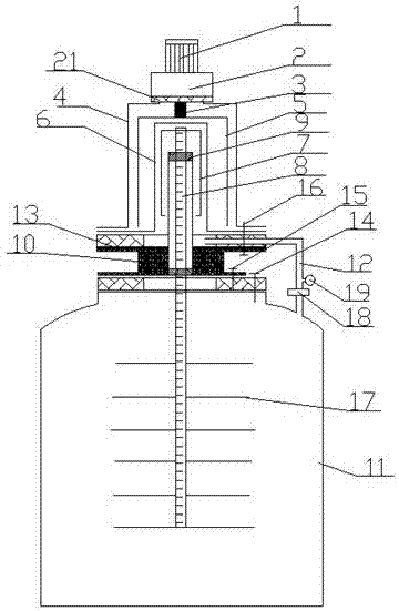
[0016] This embodiment provides a novel anti-clogging reactor, such as figure 1 As shown, the reactor is mainly composed of a motor 1, a reducer 2, an output shaft 3, an outer cover 4, an outer magnetic cylinder 5, a sealing cover 6, an inner magnetic cylinder 7, a rotating shaft 8, a bearing 9, a bearing seat 10, and a flange 13 , kettle cavity 11, pipeline 12 and stirring blade 17, the motor 1 is connected to the top of the output shaft 3 through the reducer 2, and the bottom end of the output shaft 3 passes through the outer cover 4 and is connected to the outer magnetic cylinder 5 located in the outer cover 4, The top of the outer cover 4 is fixedly connected with the reducer 2 through the third flange 21, the sealing cover 6 is located in the outer magnetic cylinder 5, the inner magnetic cylinder 7 is located in the sealing cover 6, and the inner magnetic cylind...


PUM


Abstract

The invention relates to the field of reactors and discloses a novel anti-clogging reactor. A motor (1) is fixedly connected with the top end of an output shaft (3) by virtue of a reducer (2); the bottom end of the output shaft penetrates through an outer cover (4) and then is connected with an outer magnetic cylinder (5); the outer magnetic cylinder is positioned in the outer cover; a sealing cover (6) is positioned in the outer magnetic cylinder; an inner magnetic cylinder (7) is positioned in the sealing cover and fixedly connected with the top of a rotating shaft (8); the bottom end of therotating shaft stretches into a reactor chamber (11); a bearing (9) is arranged at the periphery of the rotating shaft in a sleeving manner; a bearing housing is arranged at the periphery of the bearing in a sleeving manner; the sealing cover is connected with the upper surface of the bearing housing in a sealed manner; the lower surface of the bearing housing is connected with an opening in thetop of the reactor chamber; and a pipeline 12 is communicated with the reactor chamber and the sealing cover. Compared with the prior art, the novel anti-clogging reactor disclosed by the invention has the advantages that feed liquid in the reactor chamber can be effectively prevented from entering the sealing cover so as not to block the inner magnetic cylinder, and damage of the inner magnetic cylinder due to blockage of the feed liquid is avoided.

Description

technical field [0001] The invention relates to the field of reactors, in particular to a novel anti-clogging reactor. Background technique [0002] In chemical fields such as pesticides and pharmaceuticals, reactors are the most common production equipment. Most of the reactors need to process feed liquids with a certain temperature. Due to the sealed environment in the reactor cavity, the feed liquids will be separated while stirring in the reactors. Due to the action of pressure, it rushes up to the bearing position in the kettle cavity, and the high temperature liquid will wash away the lubricating oil between the bearing and the rotating shaft, resulting in a gap between the bearing and the rotating shaft. The gap between the shafts enters the upper sealing cover. Since the inner magnetic cylinder is located in the sealing cover, the material liquid entering the sealing cover will block the inner magnetic cylinder, which will cause damage to the inner magnetic cylinder ...

Claims


Application Information

Patent Timeline
Patent Type & Authority Applications(China)
IPC IPC(8): B01J19/18B01J19/00
CPCB01J19/18B01J19/002B01J19/0053B01J19/006
Inventor 张守平陈卫东
Owner GUANNAN YISITE CHEM
Learn More