
Electrical connector

A technology of electrical connectors and grounding terminals, which is applied in the field of electrical connectors that can improve high-frequency problems, can solve the problems of small shielding sheet specifications, shortened service life, and impact on durability, and achieve good stability, improved service life, and The effect of not getting tired easily

Inactive Publication Date: 2018-05-04
DEYI PRECISION ELECTRONIC IND CO LTD PANYU
View PDF5 Cites 1 Cited by
  • Summary
  • Abstract
  • Description
  • Claims
  • Application Information

AI Technical Summary

Problems solved by technology

However, there are fewer and fewer existing electrical connectors, so the specifications of the shielding sheet are also fewer and fewer. The length of the first and second elastic arms is only less than or equal to half the width of the opening, and their elasticity is insufficient when they contact the ground terminal. Tired easily, affecting durability and shortening service life

Method used


Image

  • Electrical connector
  • Electrical connector
  • Electrical connector

Examples


Embodiment Construction

[0036] In order to facilitate a better understanding of the purpose, structure, features, and effects of the present invention, the present invention will now be further described in conjunction with the accompanying drawings and specific embodiments.

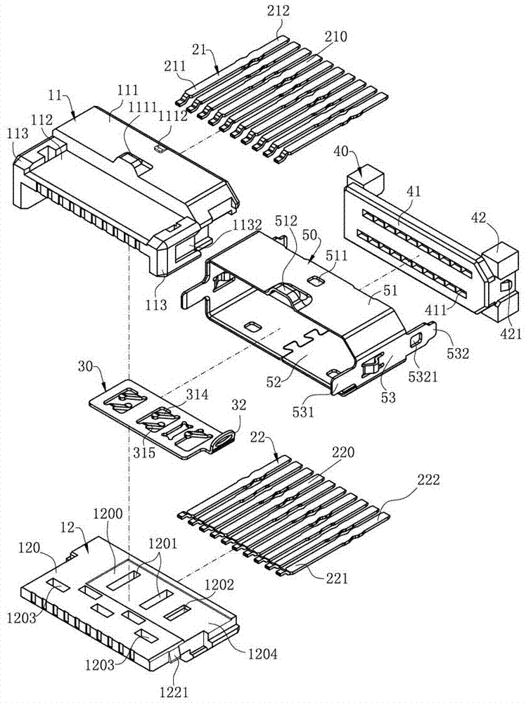
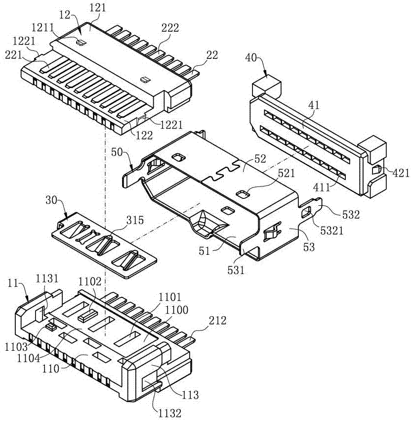
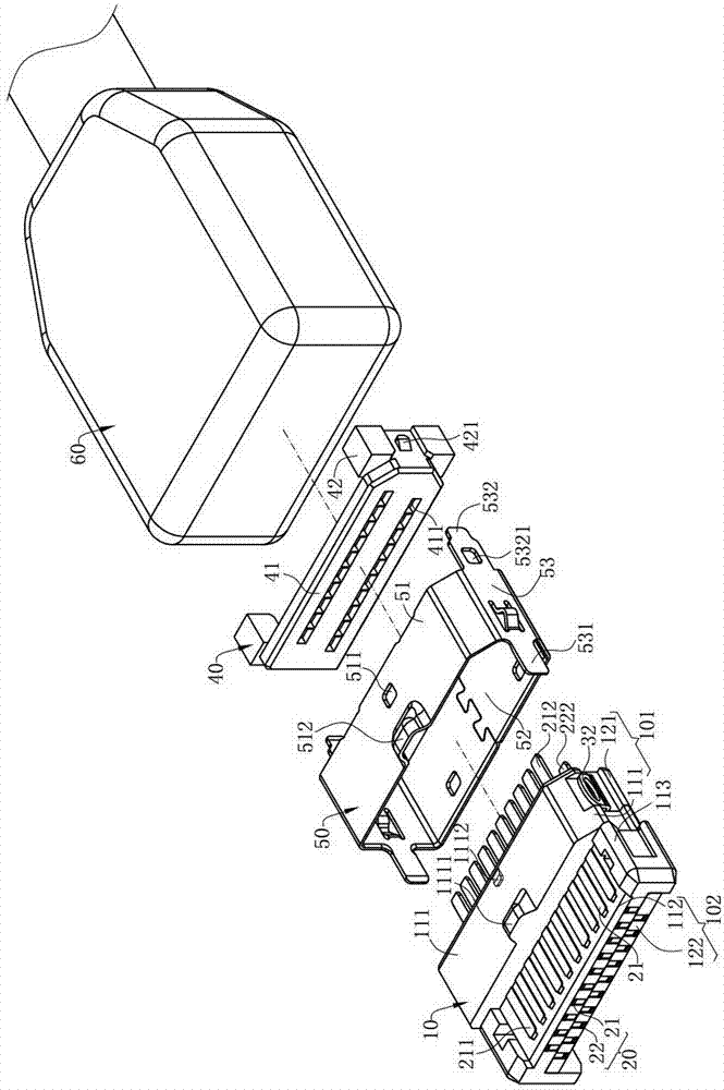
[0037] Please refer to Figure 1 to Figure 8 , is the main embodiment of an electrical connector 100 of the present invention, which includes an insulating body 10, a plurality of terminals 20 accommodated in the insulating body 10, a shielding sheet 30, an insulating member 40 and a metal shell 50 and a plastic shell 60 .

[0038] Please refer to Figure 1 to Figure 4 and Figure 8, the insulating body 10 has a base 101, a tongue 102 extending forward from the base 101, and the tongue 102 has upper and lower surfaces opposite to each other. The insulating body 10 is assembled by stacking an upper insulating body 11 and a lower insulating body 12 up and down. The upper insulating body 11 is provided with a first inner wall 1...


PUM


Abstract

The present invention discloses an electrical connector. The electrical connector comprises an insulation body. Multiple terminals comprise an upper row terminal group and a lower row terminal group,and the multiple terminals are fixed on the insulation body. The upper row terminal group comprises at least one first grounding terminal, and the lower row terminal group comprises at least one second grounding terminal. A shielding piece is contained in the insulation body, the shielding piece is located between the upper row terminal group and the lower row terminal group, and the shielding piece comprises at least an opening, a first elastic arm and a second elastic arm, wherein the first elastic arm and the second elastic arm form interlaced arrangement separately from two opposite sidesof the inner edge of the opening. The first elastic arm extends towards the first grounding terminal(s), and the first elastic arm and the first grounding terminal(s) are contacted with each other. The second elastic arm extends towards the second grounding terminal(s), and the second elastic arm and the second grounding terminal(s) are contacted with each other. The extending starting points of the first elastic arm and the second elastic arm are separately a first position and a second position, and the extending end points are separately a third position and a fourth position. The third position is more close to the second position compared with the fourth position to ensure that the elastic arm lengths of the first elastic arm and the second elastic arm are long enough, so that the first elastic arm and the second elastic arm are not prone to fatigue when the first elastic arm and the second elastic arm are contacted with the grounding terminals repeatedly, the durability is enhanced, and the service life is improved.

Description

technical field [0001] The invention relates to an electrical connector, in particular to an electrical connector capable of improving high-frequency problems. Background technique [0002] A known electrical connector, which includes an insulating body and a number of butt terminals fixed to the insulating body, including a plurality of upper row terminals and a plurality of lower row terminals, both of which have grounding terminals. A shielding sheet is arranged between the terminal row and the lower row of terminals, and an opening is arranged on the shielding sheet, and a first elastic arm and a second elastic arm extend from the opening to respectively contact the grounding terminals of the upper row and the lower row to achieve the effect of grounding. Solve high frequency problems. However, the first elastic arm and the second elastic arm extend toward each other on two opposite sides of the inner edge of the opening, so the length of the first elastic arm and the s...

Claims


Application Information

Patent Timeline
IPC IPC(8): H01R13/6585
CPCH01R13/6585
Inventor 邹小乐
Owner DEYI PRECISION ELECTRONIC IND CO LTD PANYU
Learn More