
Fume exhausting structure of oven

A technology for ovens and chimneys, which is applied in the fields of oil fume removal, roaster/barbecue grids, household heating, etc. It can solve problems such as excessive oil pollution and affect the temperature field of the oven liner, and achieve the effect of cleaning and convenience

Pending Publication Date: 2018-05-08
NINGBO FOTILE KITCHEN WARE CO LTD
View PDF0 Cites 2 Cited by
  • Summary
  • Abstract
  • Description
  • Claims
  • Application Information

AI Technical Summary

Problems solved by technology

[0003] In the prior art, since the wind blown by the blower is clean air, and the exhaust pipe discharges oil fume, when the clean air and oil fume are mixed in the smoke exhaust channel and then discharged through the smoke exhaust port on the front side of the oven, the oil fume will blow. On the entire oven door body, it is easy to cause a lot of oil stains on the surface of the door body, and the surface of the entire door body assembly needs to be cleaned; in addition, the outlet of the existing exhaust pipe is generally set at the top, so that the cold air blown by the fan is easy to flow back through the top opening Into the oven liner, affecting the temperature field of the oven liner

Method used


Image

  • Fume exhausting structure of oven
  • Fume exhausting structure of oven
  • Fume exhausting structure of oven

Examples


Embodiment Construction

[0014] The present invention will be further described in detail below in conjunction with the accompanying drawings and embodiments.

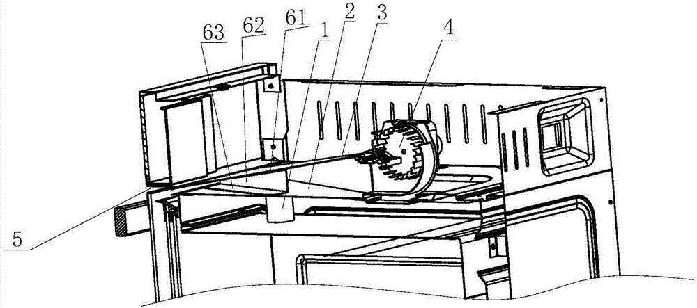
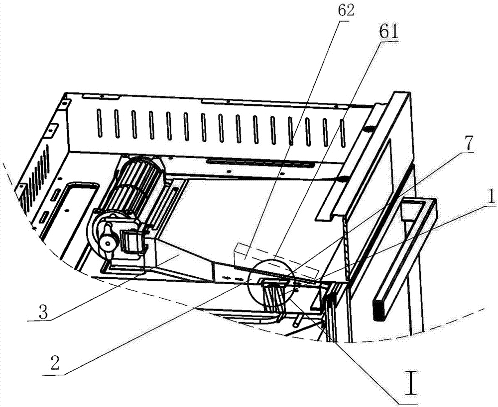
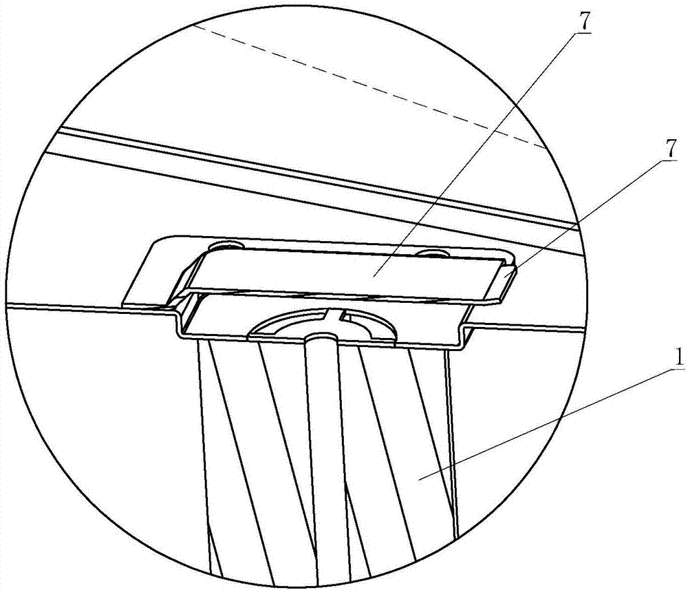
[0015] like figure 1 and figure 2 The shown smoke exhaust structure of the oven includes a smoke exhaust pipe 1 arranged at the entrance on the upper part of the oven liner and communicated with the oven liner, an upper mounting plate 2 arranged above the oven inner liner, and an upper mounting plate 2 arranged above the upper mounting plate 2 and connected to the upper A wind deflector 3 with a smoke exhaust channel is formed between the mounting plates, a fan whose air outlet communicates with the smoke exhaust channel, this embodiment is a cross-flow fan 4, and a smoke exhaust port that is arranged on the front side of the oven and communicates with the smoke exhaust channel 5. The outlet of the chimney 1 is connected to the smoke exhaust passage; a partition is arranged in the smoke exhaust passage, and the partition is arranged next to ...


PUM


Abstract

The invention relates to a fume exhausting structure of an oven. The structure includes a fume exhausting canister which is arranged at the inlet of the upper portion of an inner container of the ovenand communicated with the inner container of the oven, an upper mounting plate arranged above the inner container of the oven, an air guiding plate arranged above the upper mounting plate, a draughtfan an air outlet of which is communicated with a fume exhausting channel formed between the air guiding plate and the upper mounting plate, and a fume exhausting opening formed in the front side of the oven and communicated with the fume exhausting channel, wherein the outlet of the fume exhausting canister is communicated with the fume exhausting channel. The fume exhausting structure is characterized in that a clapboard is arranged in the fume exhausting channel and beside the outlet of the fume exhausting canister, and according to the installation position of the clapboard, air blown outby the draught fan is divided into conventional air directly exhausted from the fume exhausting opening without passing through the outlet of the fume exhausting canister, and air which is mixed withcooking fume exhausted from the inner container of the oven and passes through the outlet of the fume exhausting canister. Compared with the prior art, the fume exhausting structure has the advantagesthat only a part of an oven door body can be blown by the cooking fume, and therefore the oven is more convenient to clean.

Description

technical field [0001] The invention relates to an oven smoke exhaust structure. Background technique [0002] The smoke exhaust structure of the existing oven is mainly to set up a smoke exhaust tube on the upper part of the oven liner, and then install a fan and an air guide plate on the upper part of the oven liner, and form a smoke exhaust channel between the air guide plate and the upper mounting plate above the oven liner , the top of the front side door assembly of the oven is provided with a smoke exhaust port connected with the smoke exhaust channel, the outlet of the smoke exhaust pipe provided on the above-mentioned liner assembly is set in the smoke exhaust channel, the air outlet of the fan is connected with the smoke exhaust channel, and blown out by the fan The wind will discharge the oil fume from the chimney through the exhaust port. [0003] In the prior art, since the wind blown by the blower is clean air, and the exhaust pipe discharges oil fume, when th...

Claims


Application Information

Patent Timeline
Patent Type & Authority Applications(China)
IPC IPC(8): A47J37/06F24C15/20
CPCA47J37/0664F24C15/20
Inventor 郑德华杨均曹骥茅忠群诸永定
Owner NINGBO FOTILE KITCHEN WARE CO LTD
Learn More