Buffer valve structure

A technology of valves and buffer plates, applied in valve details, valve devices, valve operation/release devices, etc., can solve problems such as valve vibration, inconvenient parts on the valve, noise generation, etc., to reduce vibration amplitude and facilitate adjustment , the effect of convenient operation

Inactive Publication Date: 2018-05-08
陈忠义
View PDF0 Cites 2 Cited by
  • Summary
  • Abstract
  • Description
  • Claims
  • Application Information

AI Technical Summary

Problems solved by technology

[0002] Most of the valves rely on the cooperation of the valve body and the disc to control the conveying medium. After the valve is closed, the pressure at the inlet end and the outlet end are different, resulting in a pressure difference. At the moment the valve is opened, the existence of the pressure difference will cause the medium to pass through the valve. Huge instantaneous impact on valve components and pipelines, resulting in valve vibrations accompanied by noise, vibrations will affect the sealing performance, service life and other equipment used for testing of valves and pipelines connected to them, but now Some valves are inconvenient to buffer the parts on the valve, which is not conducive to the normal use of the valve, so we propose a buffer valve structure to solve the above problems

Method used


Image

  • Buffer valve structure
  • Buffer valve structure
  • Buffer valve structure

Examples


Embodiment Construction

[0017] The following will clearly and completely describe the technical solutions in the embodiments of the present invention with reference to the accompanying drawings in the embodiments of the present invention. Obviously, the described embodiments are only some of the embodiments of the present invention, not all of them.

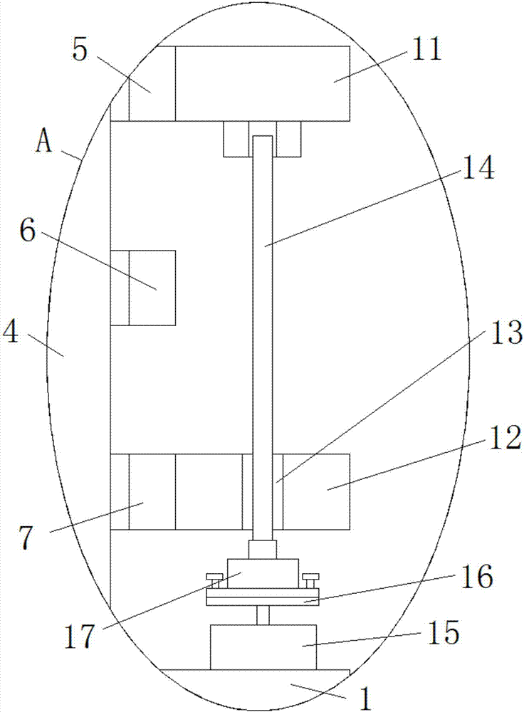
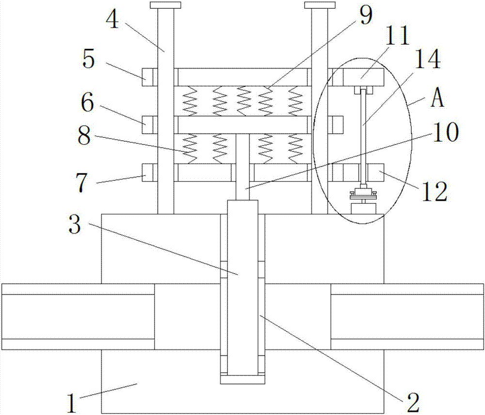
[0018] refer to Figure 1-2 , the buffer valve structure, including the valve body 1, the top of the valve body 1 is provided with an adjustment groove 2, and an adjustment plate 3 is slidably installed in the adjustment groove 2, and both sides of the top of the valve body 1 are welded with limit rods 4, two limit The outer side of the rod 4 is slidably installed with the first buffer plate 5, the second buffer plate 6 and the third buffer plate 7 in sequence from top to bottom, and the top of the third buffer plate 7 is welded with a plurality of first springs 8, and the plurality of first buffer plates The top of spring 8 is all welded with the botto...


PUM


Abstract

The invention discloses a buffer valve structure which comprises a valve body. An adjusting groove is formed in the top of the valve body, and an adjusting plate is installed in the adjusting groove in a sliding mode. Limiting rods are both welded to the two sides of the top of the valve body. A first buffer plate, a second buffer plate and a third buffer plate are sequentially installed at the outer sides of the two limiting rods from top to bottom in a sliding mode. A plurality of first springs are welded to the top of the third buffer plate. The top ends of the multiple first springs are welded to the bottom of the second buffer plate. A plurality of second springs are welded to the top of the second buffer plate. The top ends of the multiple second springs are welded to the bottom of the first buffer plate. The top of the adjusting plate extends to the upper side of the valve body and is further welded with a connecting rod. The buffer valve structure is simple in structure and convenient to operate, elastic force between the first springs and the second springs can be adjusted conveniently, the vibration frequency of the adjusting plate can be reduced, the adjusting plate canbe effectively buffered and thus the buffer valve structure can be better used by people.

Description

technical field [0001] The invention relates to the technical field of valves, in particular to a buffer valve structure. Background technique [0002] Most of the valves rely on the cooperation of the valve body and the disc to control the conveying medium. After the valve is closed, the pressure at the inlet end and the outlet end are different, resulting in a pressure difference. At the moment the valve is opened, the existence of the pressure difference will cause the medium to pass through the valve. Huge instantaneous impact on valve components and pipelines, resulting in valve vibrations accompanied by noise, vibrations will affect the sealing performance, service life and other equipment used for testing of valves and pipelines connected to them, but now Some valves are inconvenient to buffer the parts on the valve, which is not conducive to the normal use of the valve. Therefore, we have proposed a buffer valve structure to solve the above problems. Contents of th...

Claims


Application Information

Patent Timeline
Patent Type & Authority Applications(China)
IPC IPC(8): F16K31/04F16K47/00
CPCF16K31/04F16K47/00
Inventor 陈忠义
Owner 陈忠义
Why Eureka
Try Eureka