PTZ system and monitoring system

A monitoring system and pan/tilt technology, applied in the direction of machine/stand, supporting machine, mechanical equipment, etc., can solve the problems of high manufacturing and installation cost, storage, omission of important information, etc., and achieve the effect of avoiding blind spots.

Active Publication Date: 2020-02-14
杨留新
View PDF7 Cites 0 Cited by
  • Summary
  • Abstract
  • Description
  • Claims
  • Application Information

AI Technical Summary

Problems solved by technology

At an intersection, generally, the pole on which a dome camera is installed can only hold one spherical camera, but the manufacturing and installation costs of the pole are generally high. No matter whether a dome camera is inspected by a fixed point or by manual inspection, there will be monitoring blind spots. As a result, important information is missing and stored, so the existing means are often to install a bolt or ball camera near the ball camera to solve the problem of blind spots, but this also increases the cost virtually.

Method used


Image

  • PTZ system and monitoring system
  • PTZ system and monitoring system
  • PTZ system and monitoring system

Examples


Embodiment Construction

[0024] In order to make the purpose, technical solutions and advantages of the embodiments of the present invention clearer, the technical solutions in the embodiments of the present invention will be clearly and completely described below in conjunction with the drawings in the embodiments of the present invention. Obviously, the described embodiments It is a part of embodiments of the present invention, but not all embodiments. The components of the embodiments of the invention generally described and illustrated in the figures herein may be arranged and designed in a variety of different configurations.

[0025] Accordingly, the following detailed description of the embodiments of the invention provided in the accompanying drawings is not intended to limit the scope of the claimed invention, but merely represents selected embodiments of the invention. Based on the embodiments of the present invention, all other embodiments obtained by persons of ordinary skill in the art wi...


PUM


Abstract

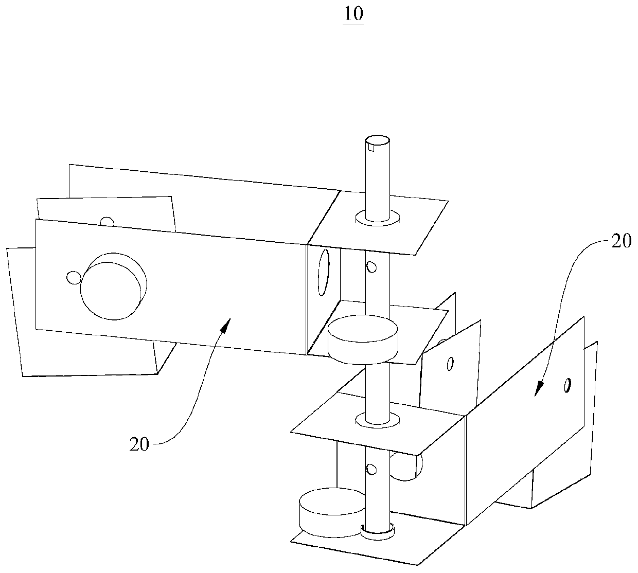
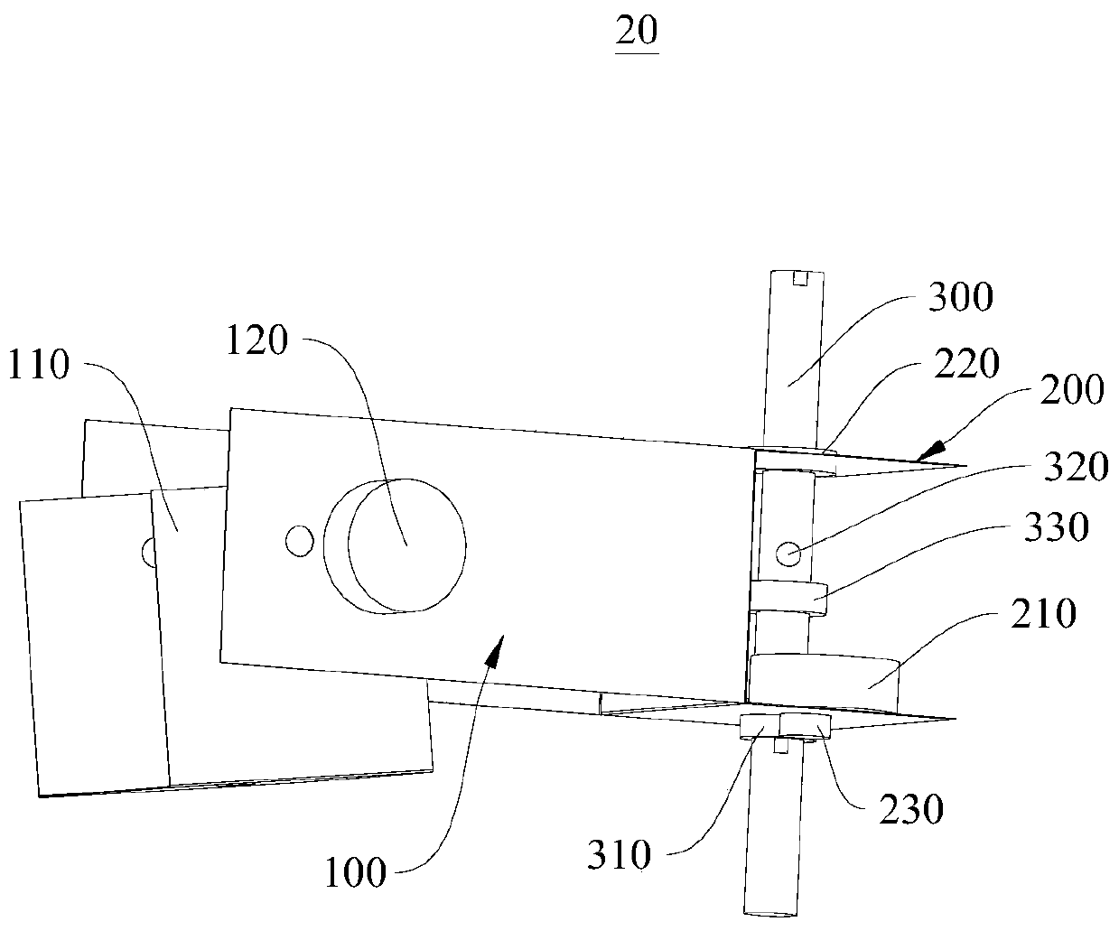
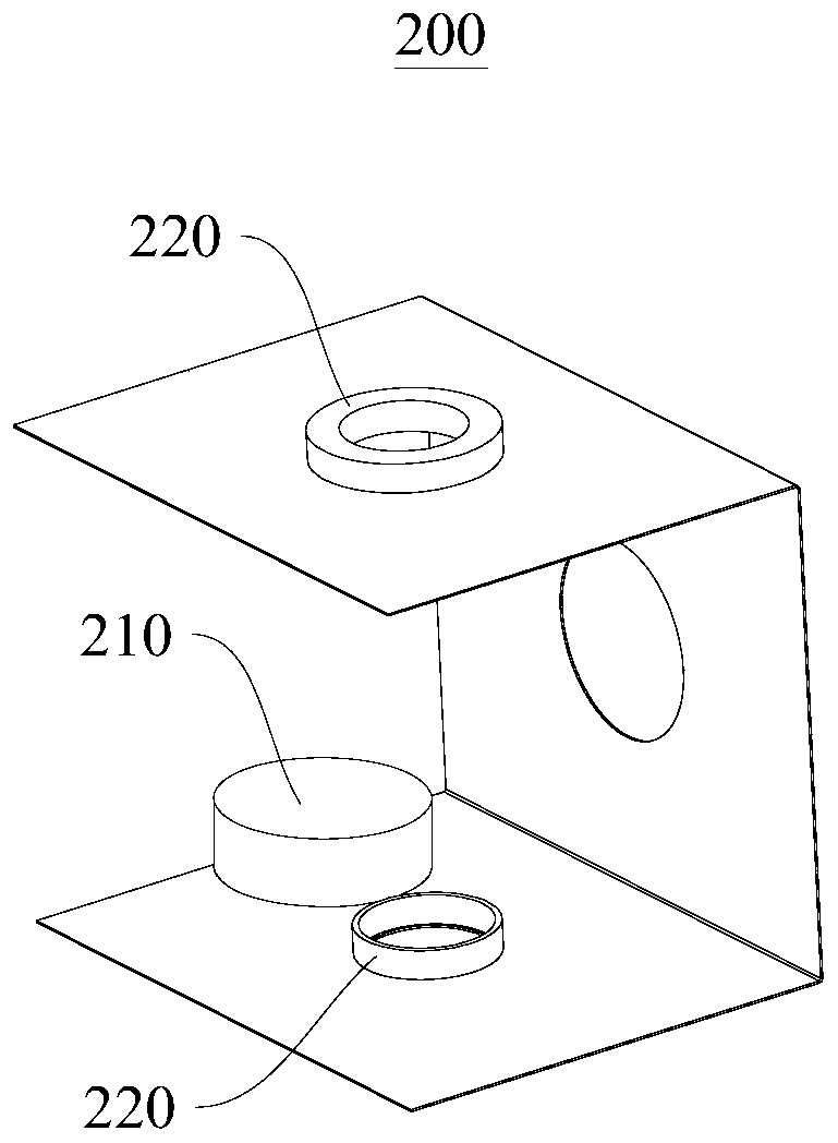
A pan-tilt system (10) and a monitoring system. The pan-tilt system (10) comprises a plurality of interconnected pan-tilts (20), each pan-tilt (20) comprising a fixed shaft (300), and a first U-shaped groove (100) and a second U-shaped groove (200) which are fixedly connected to each other, any two adjacent pan-tilts (20) being connected by means of a respective fixed shaft (300). a camera base (110) is provided in the first U-shaped groove (100), the camera base (110) is configured to fix a camera, an outer side wall of the first U-shaped groove (100) is provided with a first electric motor (120), and the first electric motor (120) is connected to the camera base (110), and is configured to drive the camera base (110) to rotate; the fixed shaft (300) passes through two side walls of the second U-shaped groove (200) and is movably connected to the second U-shaped groove (200); one side wall of the second U-shaped groove (200) is provided with a second electric motor (210), and the second electric motor (210) is in transmission connection with the fixed shaft (300). The pan-tilt system (10) and the monitoring system can complete the monitoring work of the multiple intersections by means of only one upright post.

Description

technical field [0001] The invention relates to the technical field of monitoring equipment, in particular to a pan-tilt system and a monitoring system. Background technique [0002] A city surveillance system generally consists of road surveillance cameras set on each road, and each surveillance camera includes a pan / tilt and a camera. At an intersection, generally, the pole on which a dome camera is installed can only hold one spherical camera, but the manufacturing and installation costs of the pole are generally high. No matter whether a dome camera passes fixed-point inspection or manual inspection, there will be monitoring blind spots. As a result, the omission and storage of important information occurs, so the existing means are often to install a bolt or dome camera near the dome camera to solve the problem of visual blind spots, but this invisibly increases the cost. Contents of the invention [0003] The purpose of the present invention is to provide a pan-tilt...

Claims


Application Information

Patent Timeline
Patent Type & Authority Patents(China)
IPC IPC(8): F16M13/02F16M11/16
CPCF16M11/16F16M13/02
Inventor 杨留新
Owner 杨留新
Why Eureka
Try Eureka