A self-locking device for safe insertion and extraction of plug-in circuit breakers

A technology for pulling out self-locking and circuit breakers, which is applied in the direction of emergency protection devices, circuits, protection switch operation/release mechanisms, etc. It can solve the problems of unreliable prevention of circuit breaker insertion or pull-out of circuit breakers, etc., and achieve the effect of increasing the fulcrum

Active Publication Date: 2020-02-21
SHANGHAI LIANGXIN ELECTRICAL
View PDF6 Cites 0 Cited by
  • Summary
  • Abstract
  • Description
  • Claims
  • Application Information

AI Technical Summary

Problems solved by technology

Chinese patent 201010263989.7 discloses a plug-in molded case circuit breaker safety plug-in self-locking device, which includes a circuit breaker body, which is provided with an operating mechanism. The operating mechanism includes a connecting rod that can rotate around the rotating shaft. There is a limit step, the limit piece is rotatably installed on a fixed shaft, the limit piece has a connecting arm and a limit arm, the connecting arm is provided with a waist-shaped hole, and a linkage shaft is passed through In the waist-shaped hole and connected to one end of the connecting rod, the bracket is fixed on the bottom of the circuit breaker body, the lock is installed on the bracket for rotation, and the spring is connected between the lock and the bracket. The self-locking device uses a self-locking point in the It is forbidden to insert or pull out the circuit breaker from the base when it is in the closed state. This structure has only one independent fulcrum, which cannot reliably prevent the circuit breaker from being inserted or pulled out when the circuit breaker is tilted to one end, and there is a risk of failure

Method used


Image

  • A self-locking device for safe insertion and extraction of plug-in circuit breakers
  • A self-locking device for safe insertion and extraction of plug-in circuit breakers
  • A self-locking device for safe insertion and extraction of plug-in circuit breakers

Examples


Embodiment

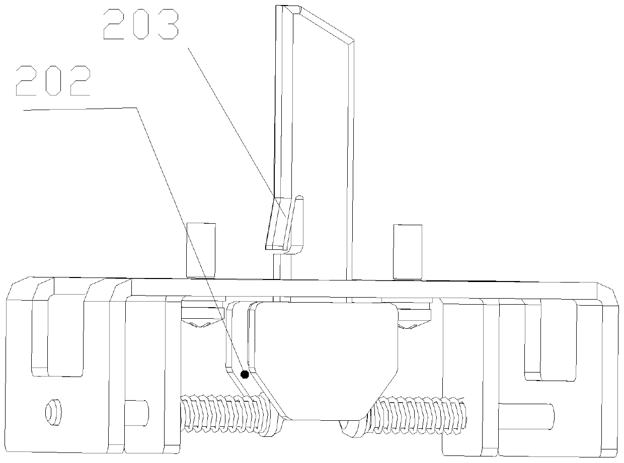
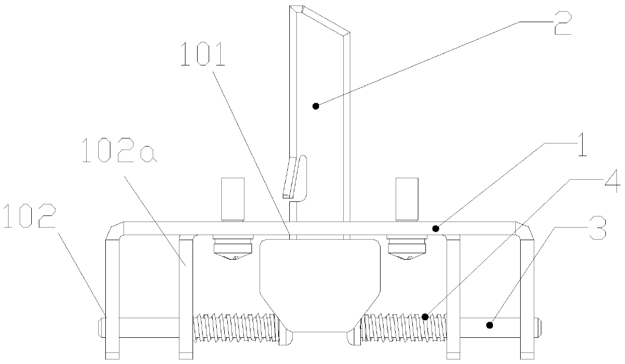
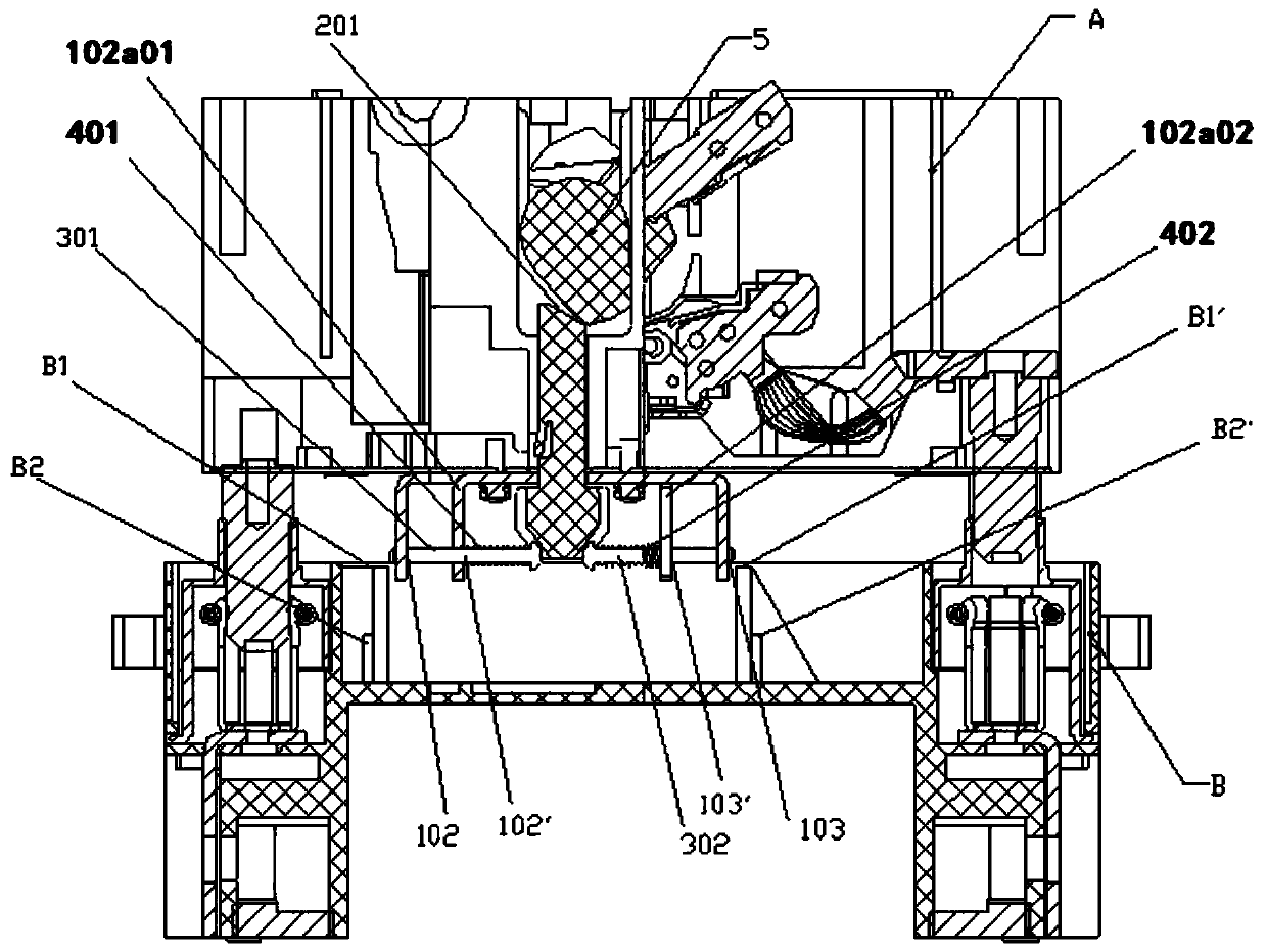
[0024] as attached figure 1 and 2 As shown, a self-locking device for plug-in circuit breaker safety plug-in, which includes a bracket 1, a connecting rod 2 installed in the sliding hole 101 of the bracket 1, the lower end of the connecting rod 2 is linked with the ejector rod 3, and the ejector rod 3 is installed horizontally in the mounting hole 102 of the bracket 1, and the spring 4 is set on the ejector rod 3. The head end of the ejector rod 3 is linked with the lower end of the bracket 1, and the connecting rod 2 can push the ejector rod 3 during the up and down movement in the sliding hole 101. horizontal linear movement;

[0025] The bracket 1 is fixedly mounted on the circuit breaker body A, the upper end of the connecting rod 2 is an inclined surface 201, the rotating shaft 5 of the circuit breaker is in contact with the inclined surface 201, and the rotating shaft 5 of the circuit breaker can drive the connecting rod 2 to move during the rotation process, and the co...


PUM


Abstract

The invention discloses a self-locking device for safety plugging of a plug-in type circuit breaker, and the device is characterized in that the device comprises a support (1); a connecting rod (2) isinstalled in a sliding hole (101) of the support (1); the lower end of the connecting rod (2) is linked with a push rod (3) which is horizontally disposed in an installation hole (102) of the support(1); the push rod (3) is sleeved by a spring (4), and the head of the push rod (3) is linked with the lower end of the support (1); the connecting rod (2) can drive the push rod (3) to make horizontal linear movement in a process that the connecting rod (2) moves up and down in the sliding hole (101). According to the invention, the rotating motion of a conventional self-locking linkage mechanismis changed into translation, thereby improving the stability of the conventional self-locking linkage mechanism, increasing the self-locking support points of a self-locking mechanism, and guaranteeing that a self-locking device causes no failure even if the circuit breaker is plugged in an inclined manner.

Description

technical field [0001] The invention belongs to the technical field of circuit breakers, and in particular relates to a self-locking device for safe insertion and extraction of plug-in circuit breakers. Background technique [0002] The plug-in circuit breaker can separate or connect the circuit breaker and the socket by plugging in and out, which brings convenience to use and maintenance. For operator safety, regulations do not allow unplugging or plugging in while the circuit breaker is energized. The usual approach is to make sure the breaker is off when it is about to be plugged into or about to be unplugged from an outlet. [0003] In order to meet the requirement that the circuit breaker cannot be plugged into or pulled out of the plug-in base in the closed state, there are two traditional solutions. The first is to require the circuit breaker to automatically insert or pull out the plug-in base even in the closed state Tripping; the second is that the plug-in and pu...

Claims


Application Information

Patent Timeline
Patent Type & Authority Patents(China)
IPC IPC(8): H01H71/10H01H71/02H01H9/20
CPCH01H9/20H01H71/02H01H71/10
Inventor 张勇全嘉青晏国云张江
Owner SHANGHAI LIANGXIN ELECTRICAL
Why Eureka
Try Eureka