
Multi-drilling guide device for implantation

A guiding device, technology for surgery, applied in dental drilling, surgery, dental implants, etc., can solve problems that cannot be actively dealt with, and achieve the effect of increasing the degree of freedom of setting

Inactive Publication Date: 2018-05-11
GENOSS
View PDF6 Cites 0 Cited by
  • Summary
  • Abstract
  • Description
  • Claims
  • Application Information

AI Technical Summary

Problems solved by technology

[0006] Even so, the above-mentioned device is fixed by the length of the rod and the distance between the holes (that is, the length between the fixtures), and when the distance between the fixtures varies according to the individual or the teeth, there are differences in application. The inconvenience of the length of the rod
Moreover, not only the length, but also the problem that it cannot be actively dealt with when the angle between the fixed objects changes

Method used


Image

  • Multi-drilling guide device for implantation
  • Multi-drilling guide device for implantation
  • Multi-drilling guide device for implantation

Examples


Embodiment Construction

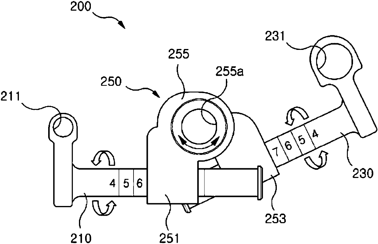
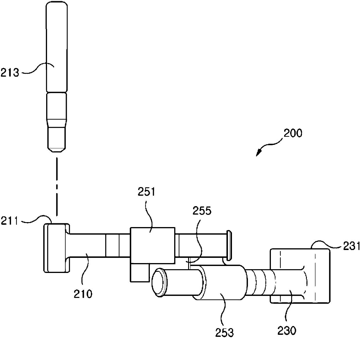
[0031] Hereinafter, a multifunctional drilling guide device for dental implant surgery according to a preferred embodiment of the present invention will be described in detail with reference to the accompanying drawings. In this specification, even if it is a mutually different Example, the same / similar structure is given the same / similar reference sign, and it replaces with the description of the first time.

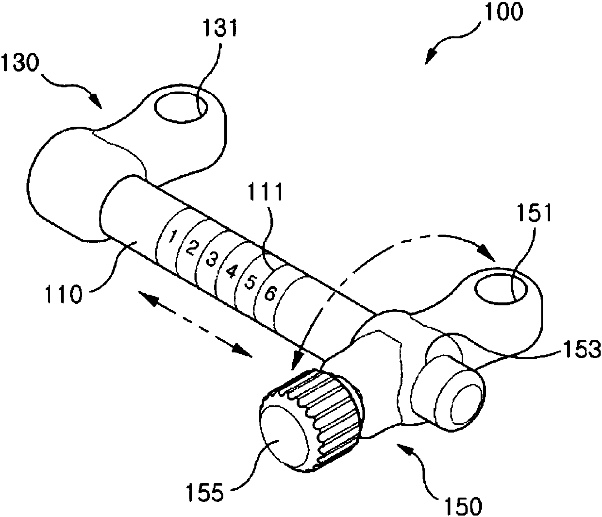
[0032] figure 1 It is a perspective view illustrating a multifunctional drilling guide device 100 according to an embodiment of the present invention.

[0033] As shown, the multifunctional drill guide device 100 may include a rod 110 , a fixing part 130 and a guiding part 150 .

[0034] The rod 110 may be formed extending along the length direction. Specifically, the rod 110 may have a shape such as a bar (Bar) extending in a linear direction. In the present embodiment, the rod 110 has a cylindrical shape, but is not limited thereto. The stem 110 may include markin...


PUM


Abstract

The present invention relates to a multi drilling guide device for operating an implant, including: a rod extending in a longitudinal direction; a fixing portion combined with one end of the rod and having a drill hole penetrating therethrough; and a guide portion coupled to the rod so as to be movable and rotatable along the rod and having a guide hole.

Description

technical field [0001] The present invention relates to a device for guiding a drill hole during implantation of an implant fixture. Background technique [0002] Generally speaking, dental implant surgery is to place artificial tooth roots behind the alveolar bone to fix artificial teeth to replace the tooth roots damaged by diseases and accidents. [0003] The dental implant surgery in which the fixture is used as the artificial tooth root should be implanted in a safer and more accurate position. Accordingly, the exact position of the artificial tooth root to be implanted needs to be determined before the operation. [0004] However, the fixture is generally implanted at an approximate position determined by the operator's experience or judgment. In this case, there is a problem that the accuracy of the implantation of the fixation is determined by the competence of the operator. [0005] In order to solve the above-mentioned problems, a support frame having a length c...

Claims


Application Information

Patent Timeline
Patent Type & Authority Applications(China)
IPC IPC(8): A61C8/00A61C3/02A61B17/17
CPCA61B17/17A61C8/0048A61C1/084A61B17/176A61C3/02A61C8/0089
Inventor 郑性旻李成根徐承佑
Owner GENOSS
Learn More