Fanner

An electric fan and air supply technology, which is applied in the field of electric fans, can solve the problems of short circuit of the control board and damage to the control circuit, and achieve the effects of improved assembly workability and low cost

Inactive Publication Date: 2008-01-30
SANYO ELECTRIC CO LTD
View PDF4 Cites 0 Cited by
  • Summary
  • Abstract
  • Description
  • Claims
  • Application Information

AI Technical Summary

Problems solved by technology

[0004] In addition, when liquids such as water are spilled on the base by mistake, the liquid enters the base from the hole formed on the base and wets the control substrate, which may short-circuit the control substrate and damage the control circuit.

Method used


Image

  • Fanner
  • Fanner
  • Fanner

Examples


Embodiment Construction

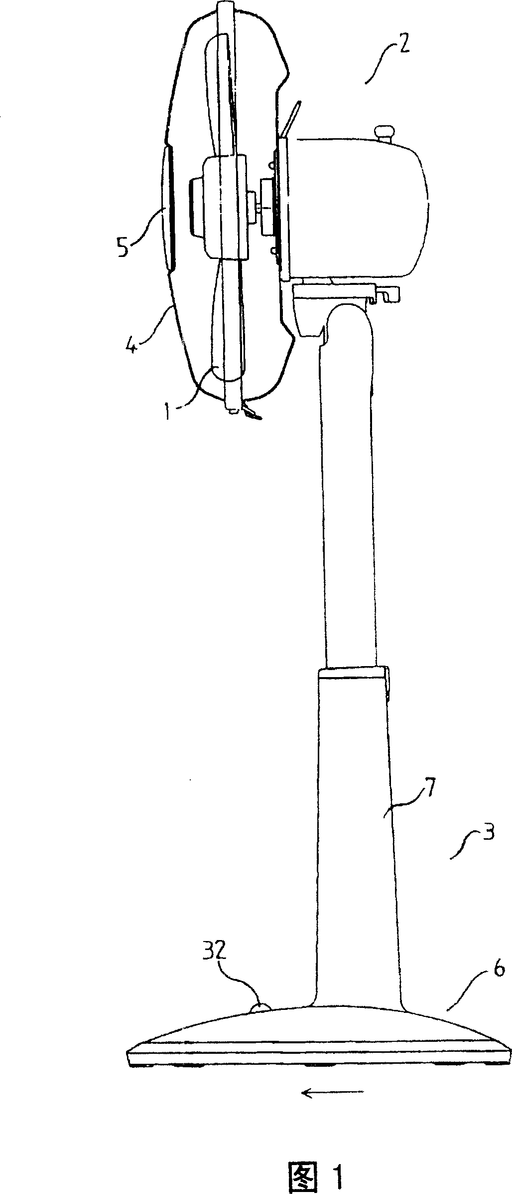
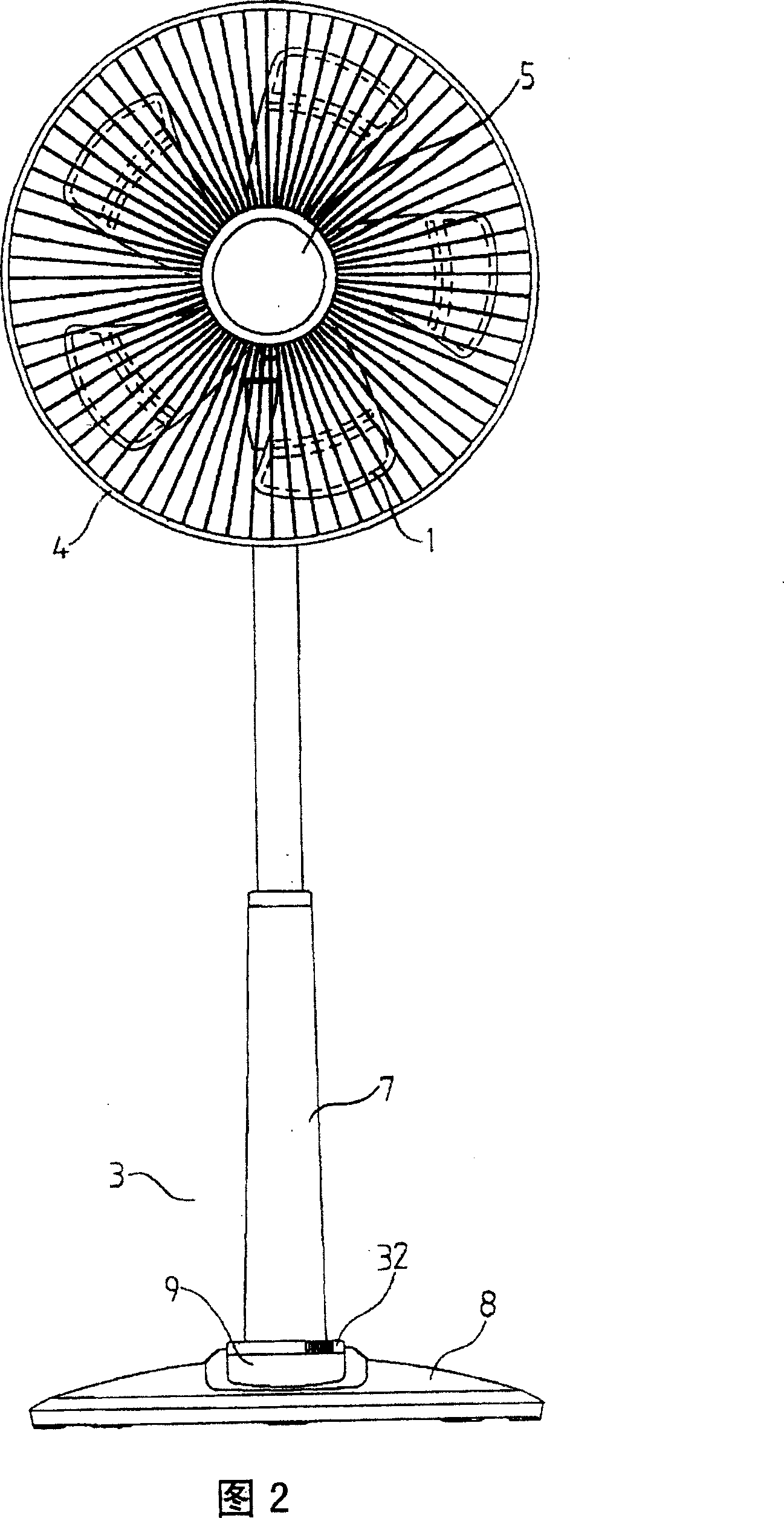
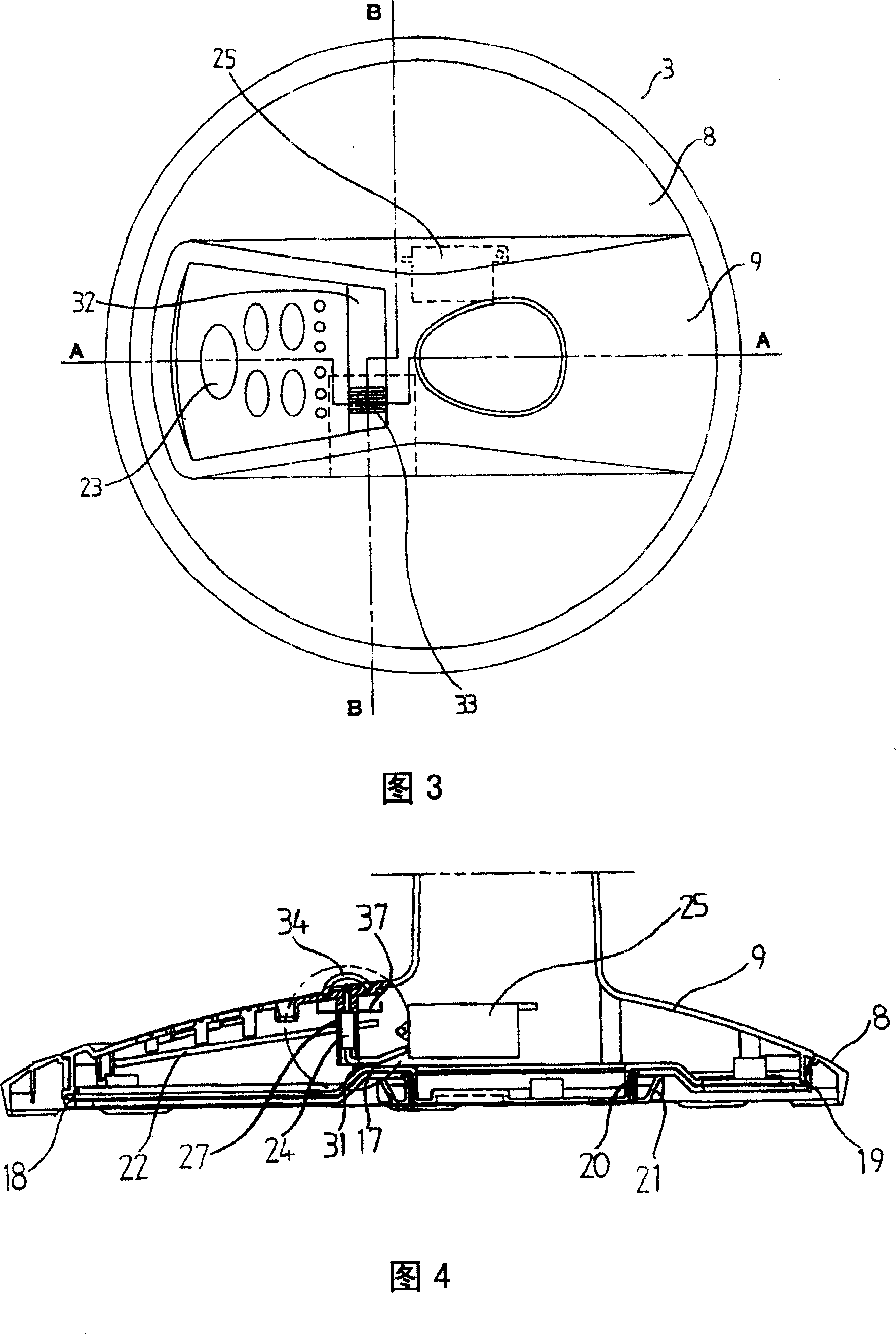
[0044] Hereinafter, the present invention will be described in detail with reference to the drawings. Fig. 1 is a side view of an electric fan according to an embodiment of the present invention. Figure 2 is a front view. FIG. 3 is a plan view of the base portion 3 . Fig. 4 is a sectional view taken along line A-A in Fig. 3 . Fig. 5 is an enlarged view of main parts in Fig. 4 . Fig. 6 is a sectional view taken along line B-B in Fig. 3 . FIG. 7 is a plan view of the first base body 8 of the present invention. FIG. 8 is a top view of the bottom cover 17 of the present invention. In addition, for convenience of description, the direction of the arrow in FIG. 1 is taken as the front side.

[0045] As shown in Figures 1 to 8, the electric fan is mainly composed of an air blowing part 2 provided with blades 1 and the like, and a base part 3 supporting the air blowing part 2, and the shell parts of each part are made by injection molding of resin. .

[0046] The air blower 2 ...


PUM


Abstract

The purpose of this invention is to provide an electric fan improving assembly workability of an ion discharging part and preventing a control substrate from getting wet when liquid intrudes in a base part from a hole mistakenly formed on the base part. In the electric fan provided with an ion discharging part, an installation part on which the ion discharging part is installed is formed integrally with the base part, and a prevention body preventing the ion discharging part from coming out of the installation part is formed on a bottom cover. A guide part guiding liquid such as water intruding into the base part from the hole formed on the base part to a lower part without passing through a control part is provided.

Description

technical field [0001] The present invention relates to an electric fan provided with an ion releasing unit. Background technique [0002] In such an electric fan, as a method of attaching the ion releasing part to the base part, there are two holding members sandwiching the ion releasing part from the side to hold the ion releasing part, and fitting the holding part with the base part above the control board. The method of fixing with screws after joining. (Japanese Patent Document No. 2003-093767, page 4, FIG. 4 ). [0003] However, in this method of attaching the ion releasing unit, in order to fix the ion releasing unit, in addition to a plurality of holding members, an assembly process of fixing the holding members with screws is required. [0004] Also, if liquid such as water is spilled on the base by mistake, the liquid enters the base through the hole formed on the base and wets the control substrate, which may short-circuit the control substrate and damage the co...

Claims


Application Information

Patent Timeline
Patent Type & Authority Patents(China)
IPC IPC(8): F04D25/08F04D29/00
Inventor 稻积秀吉安田正幸藤井直起
Owner SANYO ELECTRIC CO LTD
Why Eureka
Try Eureka