
Ring network system

A ring network and node technology, applied in ring networks, transmission systems, network interconnection, etc., can solve problems such as heavy burdens

Inactive Publication Date: 2011-04-27
HITACHI LTD
View PDF6 Cites 1 Cited by
  • Summary
  • Abstract
  • Description
  • Claims
  • Application Information

AI Technical Summary

Problems solved by technology

[0013] However, such setting and switching need to be performed after grasping the amount of communication traffic on each link, and it becomes a burdensome work for users such as system administrators.

Method used


Image

  • Ring network system
  • Ring network system
  • Ring network system

Examples


Embodiment Construction

[0029] Hereinafter, embodiments of the Ethernet ring network system according to the present invention will be described in detail with reference to the drawings.

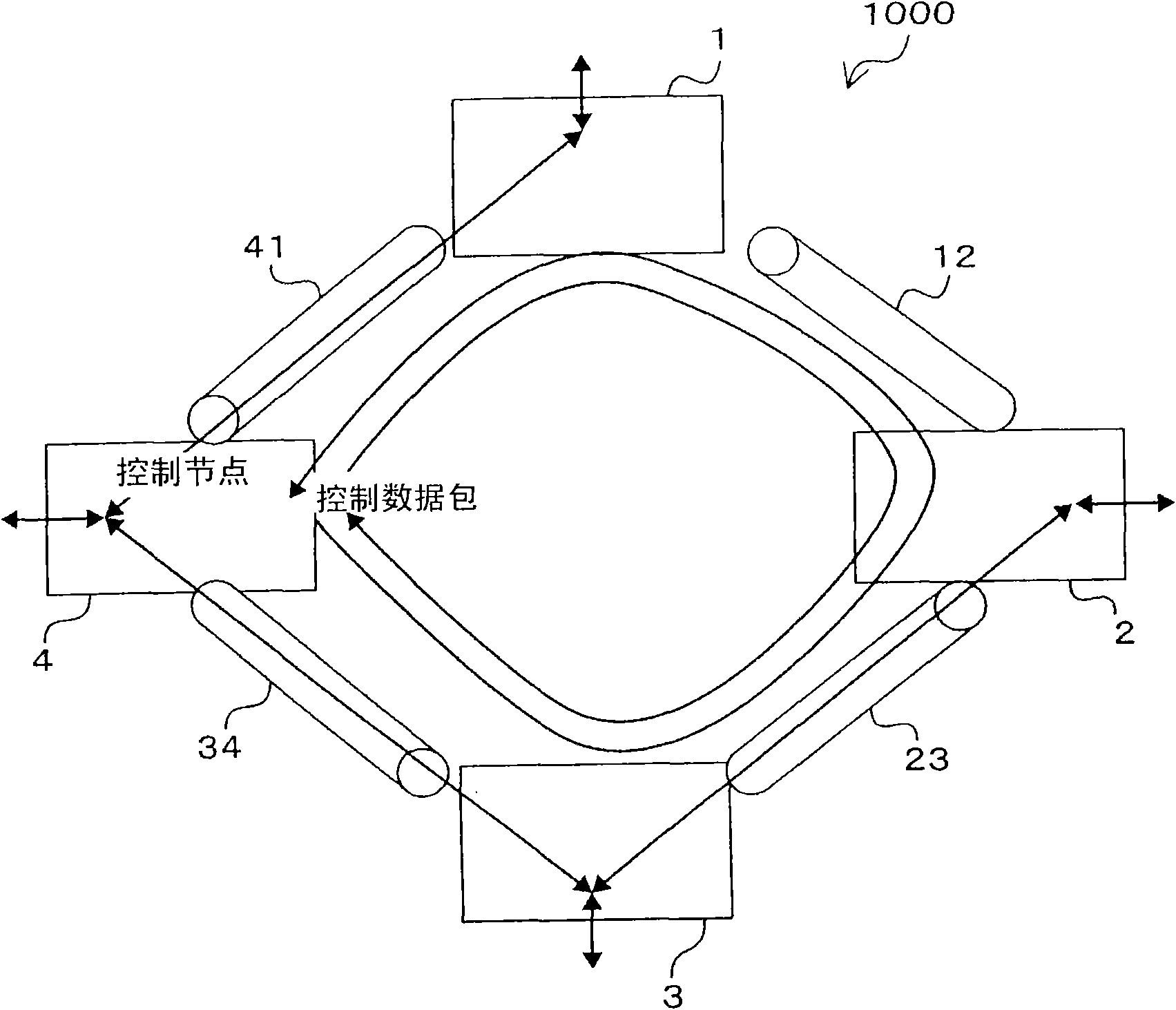
[0030] figure 1 It is a figure which shows the structure of the Ethernet ring network system 1000 which concerns on this embodiment. Such as figure 1 As shown, the Ethernet ring network system 1000 includes a plurality of non-control Ethernet switches (Ethernet switches 1-3), a control Ethernet switch 4, and links between the non-control Ethernet switches and the control Ethernet switches (chain Road 12, link 23, link 34, link 41), to form.

[0031] In addition, in the following description, a non-control Ethernet switch may be referred to as a non-control node, and a control Ethernet switch may be referred to as a control node. In addition, as described below, a non-control node when the communication path is redundant may also be referred to as a redundant node. In addition, the link 12 etc. are LAN (Local ...


PUM


Abstract

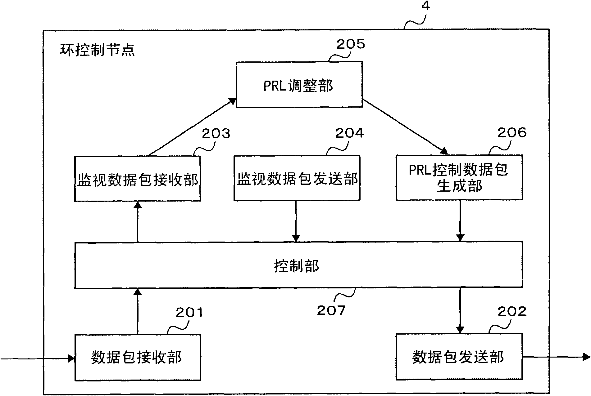
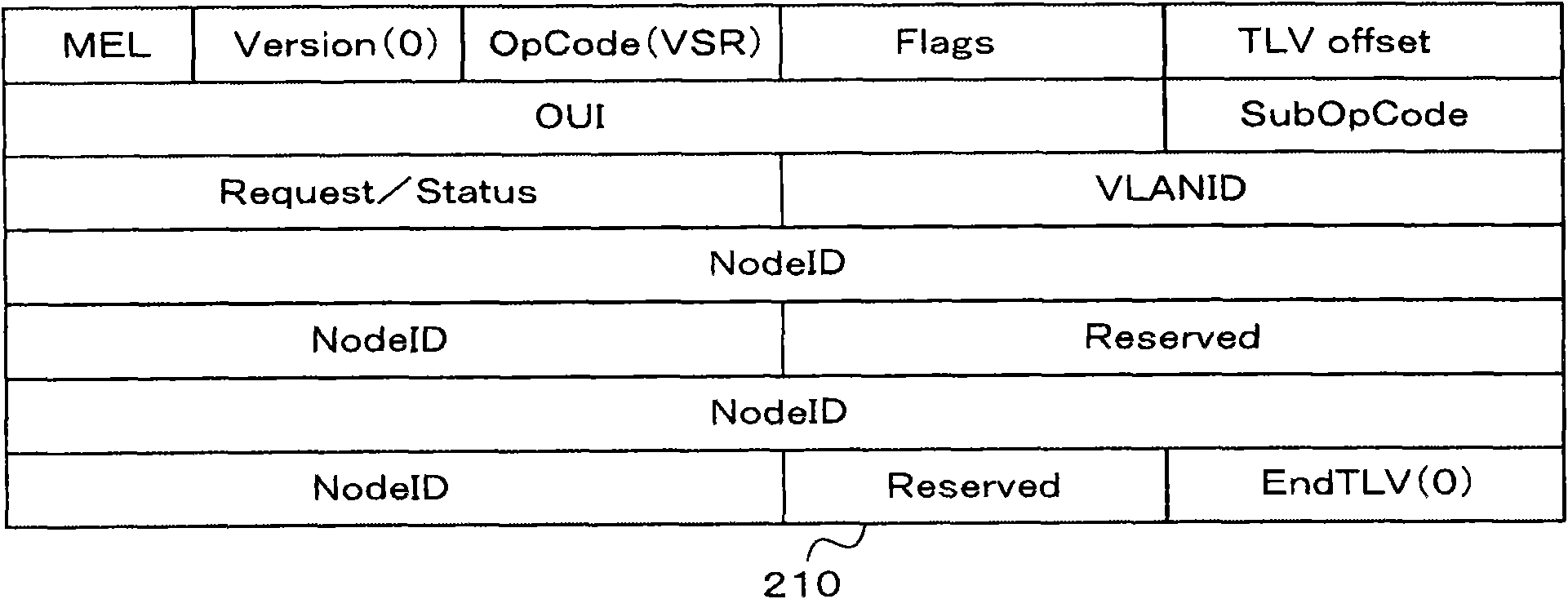
A control node includes: a monitoring packet transmission section for transmitting a monitoring packet; a monitoring packet reception section for receiving a monitoring packet; an adjustment section for selecting a redundant node from a non-control nodes; a packet generation section for generating a setup packet for specifying the redundant node out of the non-control nodes in accordance with information about the redundant node selected by the adjustment section; and a packet transmission section for transmitting the setup packet to the non-control node. The non-control node includes a control section that acquires information about the traffic upon receiving the monitoring packet, transmits a monitoring packet after acquisition of the traffic, and specifies the non-control node as the redundant node based on information about the redundant node contained in the setup packet upon receiving the setup packet.

Description

technical field [0001] The present invention relates to a ring network system for solving redundant communication paths of Ethernet (registered trademark), in particular to a ring network system implementing communication traffic dispersion in units of VLAN (Virtual Local Area Network). Background technique [0002] Conventionally, in an Ethernet system, in order to make the communication path redundant, a technique of using a ring network topology by connecting a plurality of Ethernet switches in a ring has been widely implemented. [0003] In this ring network topology, there are 2 redundant paths due to the direction of rotation of the ring (right turn and left turn). For example, when a fault occurs in a certain part of the ring, either the right-turning or left-turning path is usually blocked. When the path using the system is disconnected, the redundancy is realized by connecting the main path. Path switching. As such a technique for switching communication paths, th...

Claims


Application Information

Patent Timeline
Patent Type & Authority Applications(China)
IPC IPC(8): H04L12/437H04L12/56H04L12/46H04L12/42
CPCH04L12/4641H04L12/437
Inventor 三枝靖典清水聪中川贵之本山真也
Owner HITACHI LTD
Learn More