
Safety needle arrangement and method for drawing liquid from a body

A safety needle and assembly technology, applied in the field of safety needle assemblies, can solve problems such as adjustment elements that do not have an automatic function of needle return, and achieve the effect of avoiding accidental triggering

Active Publication Date: 2018-05-11
GREINER BIO ONE GMBH
View PDF6 Cites 0 Cited by
  • Summary
  • Abstract
  • Description
  • Claims
  • Application Information

AI Technical Summary

Problems solved by technology

However, this safety needle assembly does not have an automatically acting adjustment element for returning the needle cannula to the position that shields it

Method used


Image

  • Safety needle arrangement and method for drawing liquid from a body
  • Safety needle arrangement and method for drawing liquid from a body
  • Safety needle arrangement and method for drawing liquid from a body

Examples


Embodiment Construction

[0021] At the outset, it should be pointed out that the same reference symbols or the same component designations are used for the same components in different embodiments, wherein the disclosure content contained in the entire description can be transferred to the components with the same reference symbols or the same component designations . Likewise, orientation indications selected in the description, such as top, bottom, side, etc., relate to the directly described and illustrated figure and are transferred to the new position when the orientation changes.

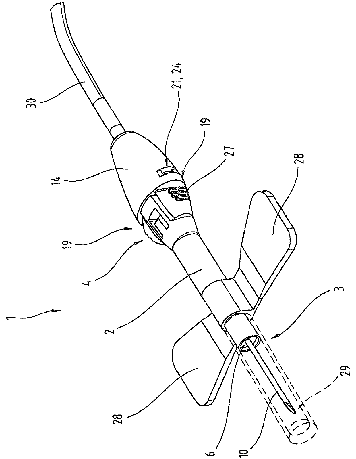
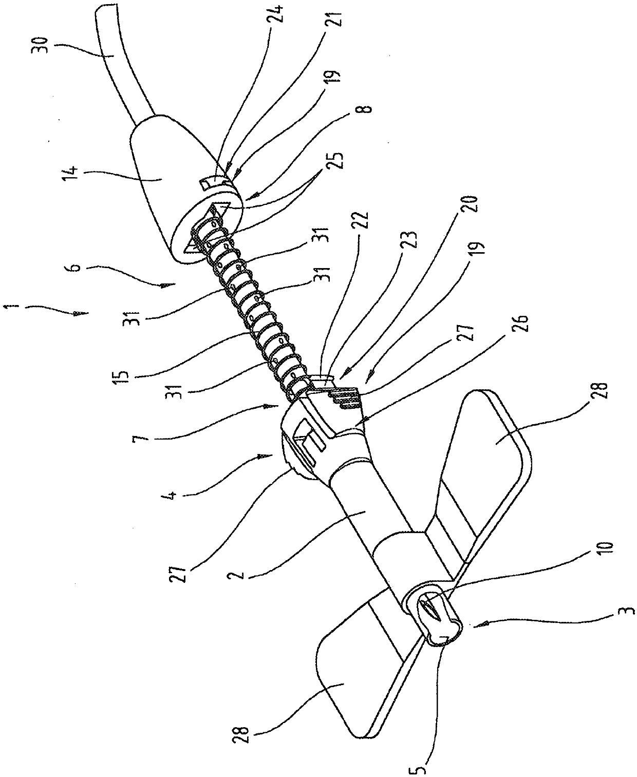
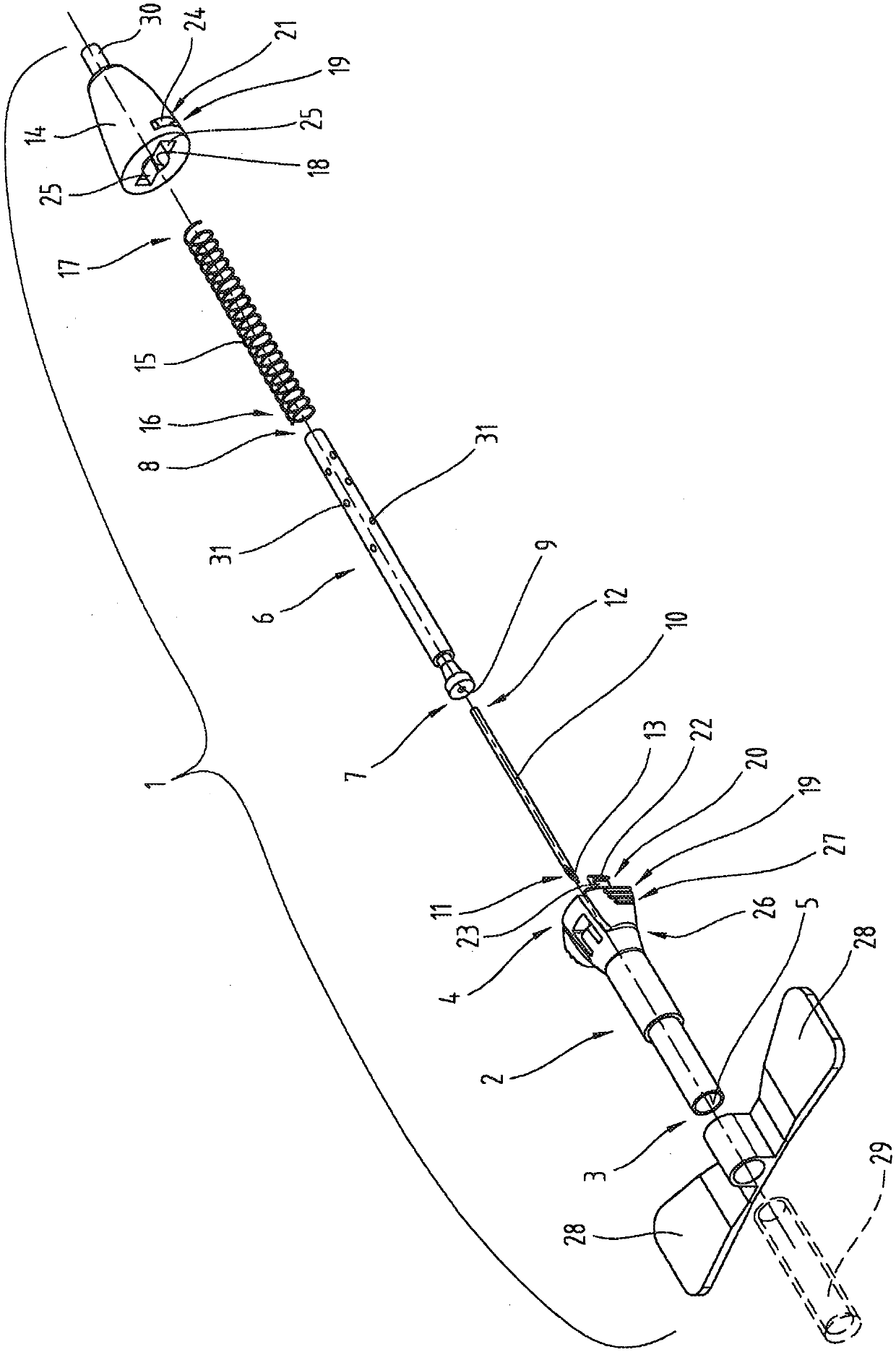
[0022] exist Figures 1 to 4 A safety needle assembly 1 used in medical technology is shown in . The safety needle assembly 1 can be used, for example, to withdraw fluids, especially blood, from the body or to inject fluids into the body. The safety needle assembly 1 constructed in this way can also be referred to as a so-called "butterfly needle". figure 1 with 2 The safety needle assembly 1 is shown in its assem...


PUM


Abstract

The invention relates to a safety needle arrangement (1) comprising a main part (2), a cannula support (6), a cannula (10), a proximal end of (12) which is held at a distal end (7) of the cannula support (6), an adjusting element (15) which is operatively arranged between the main part (2) and the cannula support (6), and a locking device (19) with multiple first and second locking elements (20, 21) which are engaged with one another. The first locking elements (20) are arranged in the region of a proximal end (4) of the main part (2) and are formed by projections (22) which are arranged diametrically opposite one another, and the second locking elements (21) are arranged in the region of a proximal end (8) of the cannula support (6) and are formed by recesses (24) which are arranged diametrically opposite one another.

Description

technical field [0001] The present invention relates to a safety needle assembly for withdrawing liquid from the body as described in claim 1 and a method for withdrawing liquid from the body as described in claim 10 . Background technique [0002] US 2007 / 0016148 A1 describes a safety needle assembly of the same type comprising a base body with a distal end and a proximal end between which a through opening extends in the base body. The safety needle assembly also includes a cannula carrier having a distal end and a proximal end, with a flow port extending between the two ends of the cannula carrier. The cannula carrier is accommodated in the through-opening of the basic body so that it can be adjusted in the axial direction. The cannula has a distal end and a proximal end between which a flow channel extends within the cannula, and the proximal end of the cannula is retained on the distal end of the cannula carrier. An adjusting element is operatively arranged between th...

Claims


Application Information

Patent Timeline
IPC IPC(8): A61M5/32A61M25/06
CPCA61M5/3257A61M25/0631A61M25/0637
Inventor C·鲍尔F·埃贝茨贝格尔F·基希迈尔A·梅尔M·C·申普尔G·斯特拉瑟
Owner GREINER BIO ONE GMBH
Learn More