
Mechanically operable valve and method for its manufacture

A technology for mechanical manipulation and manipulation elements, applied in the field of mechanically manipulated valves, which can solve the problems of inaccessibility, occupancy of valve housings, obstructions, etc.

Active Publication Date: 2019-12-27
FESTO AG & CO KG
View PDF5 Cites 0 Cited by
  • Summary
  • Abstract
  • Description
  • Claims
  • Application Information

AI Technical Summary

Problems solved by technology

The fastening bolts for the support base are well accessible here, but the resulting inaccessibility still results therein, so that the support base also occupies the side of the valve housing and is therefore obstructive in some cases.

Method used


Image

  • Mechanically operable valve and method for its manufacture
  • Mechanically operable valve and method for its manufacture
  • Mechanically operable valve and method for its manufacture

Examples


Embodiment Construction

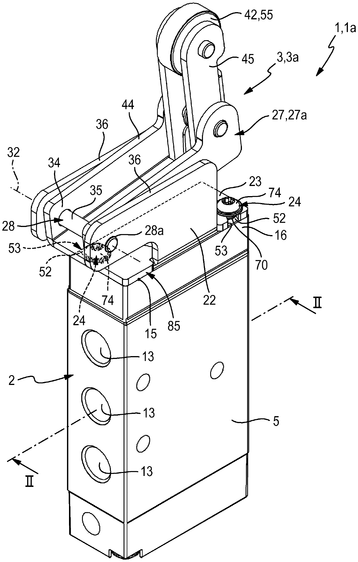
[0034] In the drawings, a mechanically actuatable valve, generally designated by the reference number 1 , is shown in the preferred embodiment of a roller lever valve 1 a.

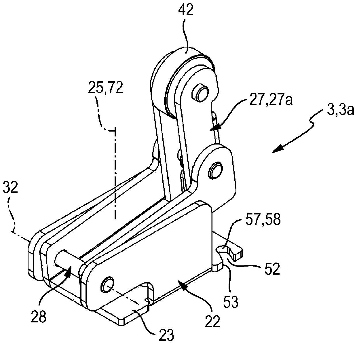
[0035] The valve 1 has a valve unit 2 and an actuating device 3 for mechanically actuating the valve unit 2 , wherein the actuating device 3 is a roller lever actuating device 3 a in the exemplary embodiment.

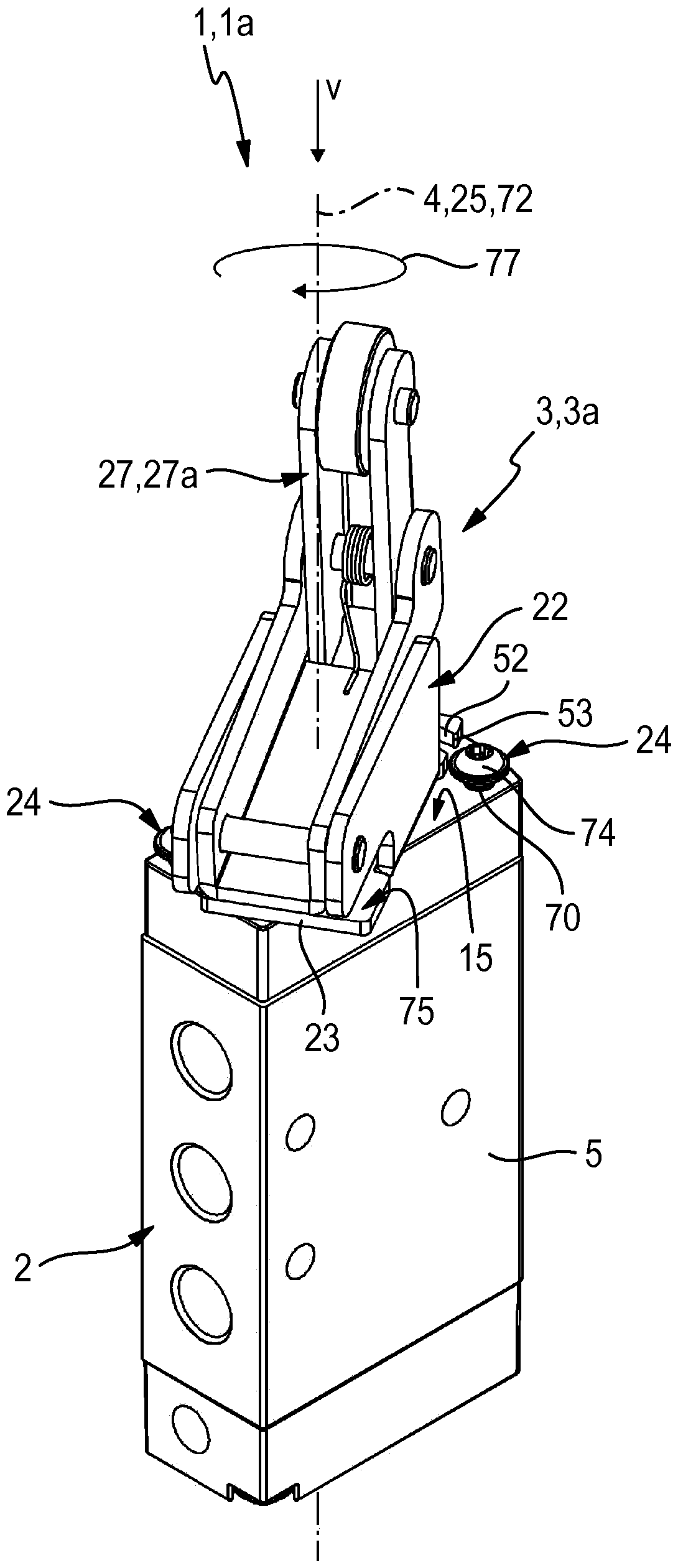
[0036] The valve unit 2 has a longitudinal axis 4 . The actuating device 3 is preferably arranged on one of the two axial end sides of the valve unit 2 pointing in the axial direction of the longitudinal axis 4 .

[0037] The valve unit 2 has a valve housing 5 in which a valve chamber 6 is formed, in which a valve mechanism assembly 7 extends. The valve mechanism assembly 7 consists in this embodiment of a single valve mechanism 7a, but may also comprise a plurality of valve mechanisms. Within the scope of the switching movement 8 indicated by the double arrow, the valve mechanism assembly 7 can b...


PUM


Abstract

The invention relates to a mechanically actuatable valve (1) having an actuation device (3) which is attached to a mounting surface (15) of a valve unit (2) by a bearing base (22). Using securing screws (24), the bearing base (22) is braced with the valve housing (5) when adopting an operating position. In order to permit a simple mounting, securing slits (52) are formed on the bearing base (22), which are open in a circumferential direction of a vertical axis (25) of the base. During mounting, the bearing base (22) can be attached to the mounting surface (15) in an attaching position that is rotated in relation to the operating position, and can then be rotated in a rotational movement (77) in such a way that the securing slits (52) are introduced under the screw heads (74) of the not-yet-tightened securing screws (24).

Description

technical field [0001] The invention relates to a mechanically actuatable valve with a valve unit having a valve housing and having a valve mechanism component which can be switched between different switching positions when a switching movement is carried out relative to the valve housing, which is characterized by The drive section protrudes from the valve housing and has an actuating device, which is placed on the mounting surface outside the valve housing with the support base in the operating position and is screwed to the valve housing and has An actuating element of the frame movement, which can be driven mechanically into an operating movement, wherein it cooperates with the drive section of the valve train assembly in order to bring about a switching movement, wherein the support base frame is at its base frame perpendicular to the assembly plane The axial direction of the vertical axis is penetrated by a plurality of fastening slots distributed around the vertical ax...

Claims


Application Information

Patent Timeline
Patent Type & Authority Patents(China)
IPC IPC(8): F16K31/524
CPCF16K31/52416F16K31/52483
Inventor H.屈鲍施F.施特恩斯
Owner FESTO AG & CO KG
Learn More