Automatic separation method and automatic separation device of cut edge material of optical diffusion plate

A technology of light diffusing plate and automatic separation, applied in optical components, metal processing, flat products, etc., can solve problems such as waste of manpower, material resources, reduced product utilization, and environmental impact of workshops

Active Publication Date: 2018-05-15
SUZHOU SANXIN TIMES NEW MATERIAL CO LTD
View PDF5 Cites 1 Cited by
  • Summary
  • Abstract
  • Description
  • Claims
  • Application Information

AI Technical Summary

Problems solved by technology

The method of saw blade cutting edge material has the following disadvantages: on the one hand, the incision of the saw blade is wider, and the utilization rate of the product is reduced; In the later stage, it is necessary to clean up the powder dust falling on the surface of the light diffusion plate
Secondly, the removed side material needs special operators to collect and process, which wastes manpower and material resources

Method used


Image

  • Automatic separation method and automatic separation device of cut edge material of optical diffusion plate
  • Automatic separation method and automatic separation device of cut edge material of optical diffusion plate
  • Automatic separation method and automatic separation device of cut edge material of optical diffusion plate

Examples


specific Embodiment example 1

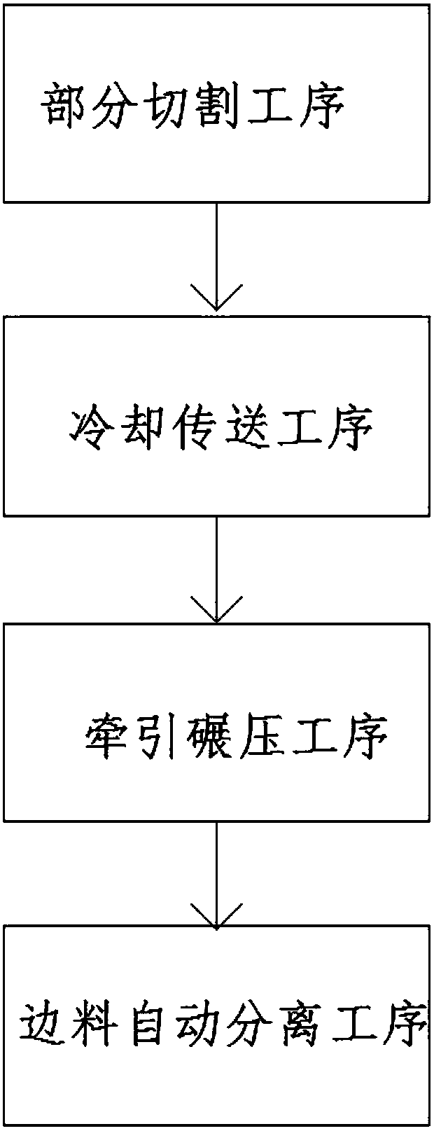
[0031] An automatic separation method for edge trimming of a light diffusion plate, specifically comprising:

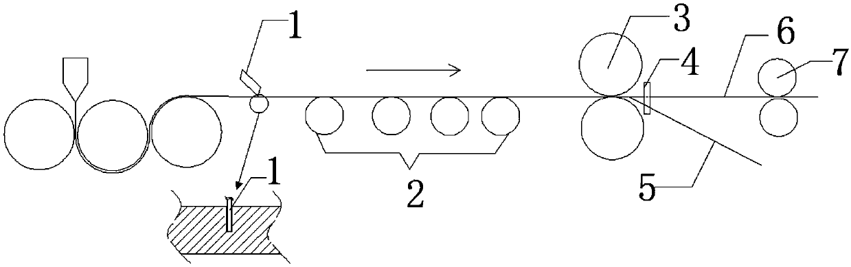
[0032] Partial cutting process: Use edge trimming device 1 to implement partial cutting process on the irregular edge material 5 on both sides of the width of the light diffusion plate after extrusion molding and surface embossing treatment, partial cutting is non-penetrating cutting, the depth of the cutting edge less than the thickness of the light diffuser. The light diffusion plate just formed is not cooled, so it is easy to cut with a thinner cutter.

[0033] Cooling and conveying process: passing the partially cut light diffusion plate through the cooling roller 2 for cooling and cooling treatment. According to the principle of thermal expansion and cold contraction, the light diffusion plates on both sides of the crack will undergo separation and contraction deformation, which will further tear the cutting edge of the knife.

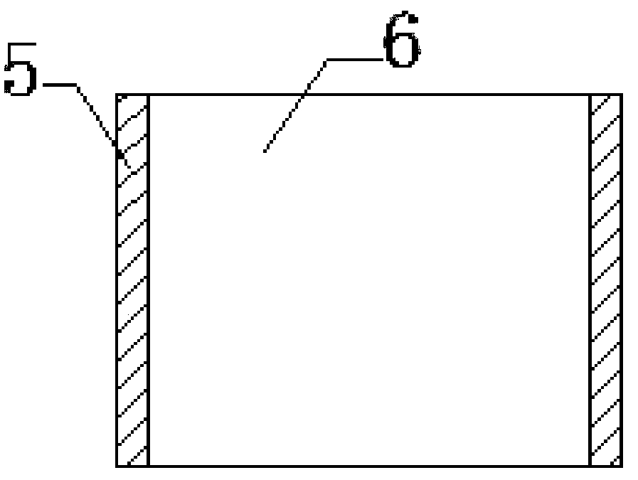
[0034] Traction and rolling proc...

specific Embodiment example 2

[0040] An automatic separation method for edge trimming of a light diffusion plate, specifically comprising:

[0041] Partial cutting process: Use edge trimming device 1 to implement partial cutting process on the irregular edge material 5 on both sides of the width of the light diffusion plate after extrusion molding and surface embossing treatment, partial cutting is non-penetrating cutting, the depth of the cutting edge less than the thickness of the light diffuser. The light diffusion plate just formed is not cooled, so it is easy to cut with a thinner cutter.

[0042] Cooling and conveying process: passing the partially cut light diffusion plate through the cooling roller 2 for cooling and cooling treatment. According to the principle of thermal expansion and cold contraction, the light diffusion plates on both sides of the crack will undergo separation and contraction deformation, which will further tear the cutting edge of the knife.

[0043] Traction and rolling proc...

specific Embodiment example 3

[0049] An automatic separation method for edge trimming of a light diffusion plate, specifically comprising:

[0050] Partial cutting process: Use edge trimming device 1 to implement partial cutting process on the irregular edge material 5 on both sides of the width of the light diffusion plate after extrusion molding and surface embossing treatment, partial cutting is non-penetrating cutting, the depth of the cutting edge less than the thickness of the light diffuser. The light diffusion plate just formed is not cooled, so it is easy to cut with a thinner cutter.

[0051] Cooling and conveying process: passing the partially cut light diffusion plate through the cooling roller 2 for cooling and cooling treatment. According to the principle of thermal expansion and cold contraction, the light diffusion plates on both sides of the crack will undergo separation and contraction deformation, which will further tear the cutting edge of the knife.

[0052] Traction and rolling proc...


PUM


Abstract

The invention discloses an automatic separation method of a cut edge material of an optical diffusion plate. The automatic separation method comprises the specific implementation steps of partial cutting procedure, cooling conveying procedure, traction rolling procedure and edge material automatic separation procedure, wherein the edge material of the optical diffusion plate is subjected to non-penetrating partial cutting through an edge cutting device; a notch between the edge material and an optical diffusion plate body is subjected to depth extension during follow-up cooling and rolling; and the edge material and the optical diffusion plate body are automatically separated through an automatic separation device. The automatic separation device comprises a supporting cross rod and separation rods, wherein one separation rod is fixed to each of length ends of the supporting cross rod through welding; the distance between the outer sides of the two separation rods is equal to the widthdimension of the optical diffusion plate body; and the separation rods right face the notch of the optical diffusion plate. According to the automatic separation method and the automatic separation device, through the cutting mode, the notch width is decreased, sawing dust is avoided, the material utilization rate is increased, cleanliness of the optical diffusion plate is guaranteed while the working environment of a workshop is improved, input of manpower and material resources is reduced, and production cost is reduced.

Description

technical field [0001] The invention relates to the technical field of mechanical equipment, in particular to an automatic separation method and an automatic separation device for edge trimming of a light diffusion plate. Background technique [0002] The light diffusion plate uses chemical or physical means to use the physical imagination of refraction, reflection and scattering when light encounters two media with different refractive indices on the way. Inorganic or organic light diffusing agents are added to the foundation, or the light is artificially adjusted through the array arrangement of the micro-feature structure on the surface of the substrate, so that the light can be refracted, reflected, and scattered in different directions, thereby changing the path of the light and realizing the full intensity of the incident light. Scattering is used to produce the effect of optical diffusion. Light diffusion plates are widely used in liquid crystal display, LED lighting ...

Claims


Application Information

Patent Timeline
Patent Type & Authority Applications(China)
IPC IPC(8): B26D3/08B26F3/02B26F3/00B29C47/08B29L7/00B29L11/00
CPCB26F3/00B26F3/02B29C48/0022B29C48/07B29C48/25B29D11/00B29L2007/002B29L2011/00
Inventor 张建林张黎明
Owner SUZHOU SANXIN TIMES NEW MATERIAL CO LTD
Why Eureka
Try Eureka