Front protection structure of electric tricycle
An electric tricycle and front protection technology, applied in the field of electric vehicles, can solve problems such as deformation, unsatisfactory cushioning performance, and inability to better protect the front wheels and users
- Summary
- Abstract
- Description
- Claims
- Application Information
AI Technical Summary
Problems solved by technology
Method used
Image

Examples
Embodiment Construction
[0016] The present invention will be further described below in conjunction with accompanying drawing.
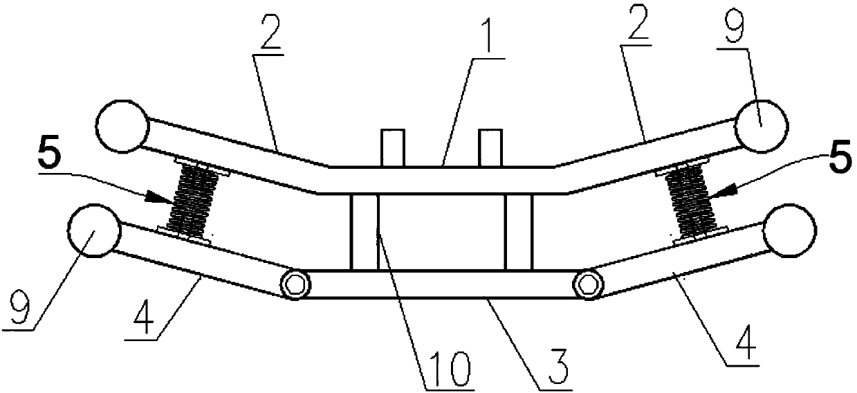
[0017] Such as figure 1 and figure 2 As shown, a front protective structure of an electric tricycle includes an inner beam 1, an inner hypotenuse beam 2 symmetrically fixedly connected to the left and right ends of the inner beam 1, an outer beam 3 and two outer hypotenuse beams 4, the inner hypotenuse The outer end of the beam 2 is close to the rear car body, the inner beam 1 and the inner bevel beam 2 are fixedly connected with the front part of the car body, the outer beam 3 is arranged at the front part of the inner beam 1, and the outer beam 3 is connected with the inner beam 3. The beams 1 are parallel, and the outer beam 3 is fixedly connected to the inner beam 1 through two connecting beams 10 perpendicular to the inner beam 1;
[0018] The inner ends of the two outer bevel beams 4 are respectively hinged with the left and right ends of the outer beam 3;
[0019...
PUM
 Abstract
Description
Claims
Application Information
 - Generate Ideas
- Intellectual Property
- Life Sciences
- Materials
- Tech Scout
- Unparalleled Data Quality
- Higher Quality Content
- 60% Fewer Hallucinations
Browse by: Latest US Patents, China's latest patents, Technical Efficacy Thesaurus, Application Domain, Technology Topic, Popular Technical Reports.
© 2025 PatSnap. All rights reserved.Legal|Privacy policy|Modern Slavery Act Transparency Statement|Sitemap|About US| Contact US: help@patsnap.com