Insulating hanging frame for live working

A technology of live work and pulley hooks, which is applied to ladders, buildings, building structures, etc., can solve problems such as time-consuming and laborious, pitching and swinging of ladder heads, and pulley hooks cannot be positioned, and achieves the effect of convenient use

Inactive Publication Date: 2018-05-15
张凤菊
View PDF1 Cites 0 Cited by
  • Summary
  • Abstract
  • Description
  • Claims
  • Application Information

AI Technical Summary

Problems solved by technology

[0004] Second, in the process of hanging the ladder head to the cable through the pulley hook, due to the adjustment of the ladder head posture and the force generated by the pull, the slope generated by the cable itself sags, resulting in the pulley hook being unable to position on the cable, often waiting for the ladder When the head reaches the position of the cable, it is not the desired position, and it needs to be adjusted continuously, which is very time-consuming and laborious, which greatly affects the work efficiency
[0006] Third, the process of hanging the ladder head on the cable is very difficult. The reason is that in actual operation, it is very difficult to fix the pull rope just in the middle of the movable cross bar, which makes the ladder head easy to tilt left and right. In the absence of a suitable fixed structure in the front and rear directions, the ladder head is prone to pitching and swinging. During the lifting process, the ladder head will rotate under the action of the torque release of the pull rope itself, resulting in the ladder head not being able to rise to the expected position at all. At the cable, even if you are lucky enough to reach the bottom of the cable, but because the connecting rod above the cable pulley is set horizontally, the result is that the connecting rod withstands the cable and cannot continue to rise

Method used


Image

  • Insulating hanging frame for live working
  • Insulating hanging frame for live working
  • Insulating hanging frame for live working

Examples


Embodiment Construction

[0031] Hereinafter, the present invention will be described in detail with reference to the drawings and examples. It should be noted that, in the case of no conflict, the embodiments of the present invention and the features in the embodiments can be combined with each other.

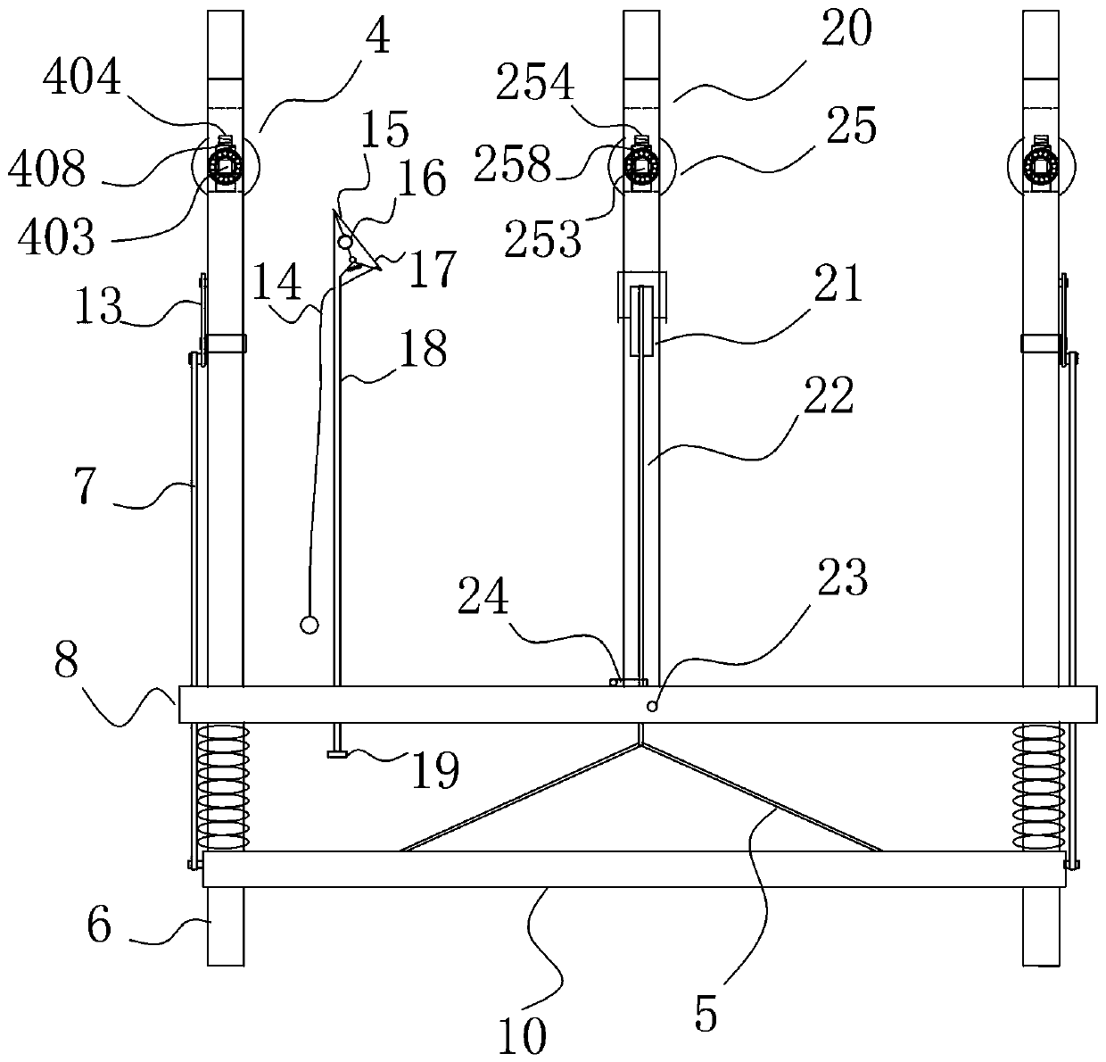
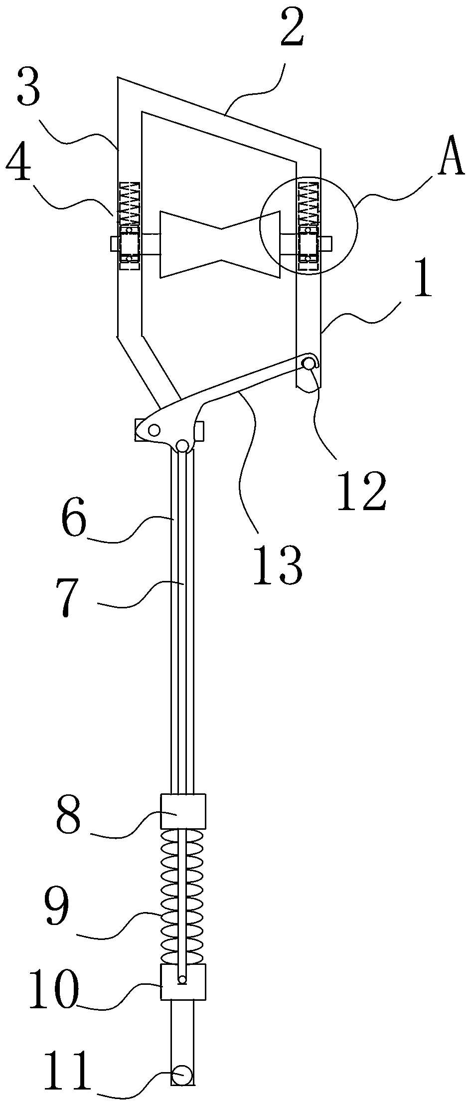
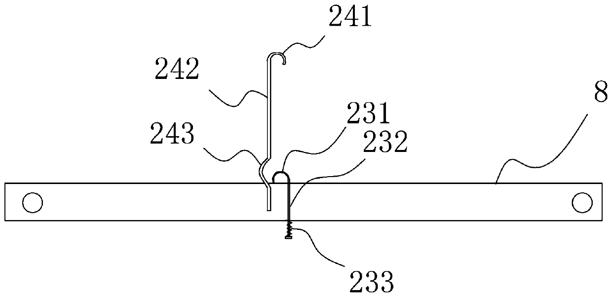
[0032] Examples of insulating hangers for live work, such as Figure 1-6 As shown, it includes two pulley brackets, a first cross bar 8, a second cross bar 10, a pulley hook 20 and a stay rope 22, and the pulley bracket includes a front bar 1, a rear bar 3, a diagonal bar 2 connecting the front bar and the rear bar , support rod 6 and the second pulley mechanism 4, the lower end of rear rod 3 is inclined inwardly and is connected with support rod 6, and the second pulley mechanism includes cable pulley 401 between front rod 1 and rear rod 3, is located at the cable pulley The second bearing 407 on the wheel shaft 402 and the second bearing installation structure, the bottom of the groove groove of the c...


PUM


Abstract

The invention relates to an insulating hanging frame for live working. The insulating hanging frame comprises two pulley brackets and a pulley hook, wherein the pulley hook comprises a font plate, a rear plate, a connecting plate and a first pulley mechanism; the first pulley mechanism comprises a pull rope pulley, a first bearing and a first bearing mounting structure; the first bearing mountingstructure comprises a first bearing containing cavity and a first compressed spring; the lower end of the first compressed spring and an outer ring of the first bearing are fixed and are used for connecting the first bearing; first guide seams are arranged at left and right sides of the first bearing containing cavity; a first rotation stopping groove is formed in the upper part of each first guide seam; a first rotation stopping part, which is matched with the first rotation stopping groove, is arranged at a position, corresponding to the first rotation stopping groove, of a pull rope pulleyshaft. The insulating hanging frame for the live working, provided by the invention, has the beneficial effects that the compressed spring with suitable length and elastic force is selected accordingto requirements; the pull rope pulley, lapped on a cable, of the pulley hook stops rotating and the position of the pull rope pulley does not move any more, so that a ladder head can be conveniently pulled to the needed cable position.

Description

technical field [0001] The invention belongs to the field of electric equipment, in particular to an insulating hanger for live work. Background technique [0002] Chinese patent document ZL201320806144.7 discloses an insulating hanger for live work, including a ladder head and a soft ladder. At both ends of the fixed cross bar, the movable cross bar is located under the fixed cross bar, and the two ends of the fixed cross bar are respectively set on two pulley brackets. The movable cross bar is connected with the fixed cross bar through a spring, and the pulley hook is located on the fixed cross bar. Above, one end of the stay rope is fixed in the center of the movable cross bar, and the other end of the stay rope passes through the fixed cross bar and the pulley hook successively, and the stay rope can drive the movable cross bar to move. The top of the pulley bracket is provided with a cable pulley, and the bottom of the cable pulley is provided with a self-locking part....

Claims


Application Information

Patent Timeline
Patent Type & Authority Applications(China)
IPC IPC(8): E06C7/50
CPCE06C7/505
Inventor 张凤菊
Owner 张凤菊
Why Eureka
Try Eureka