Bilateral driving type annular guide rail chip transmission device

An annular guide rail, bilateral drive technology, used in transportation, packaging, conveyors, etc., can solve the problem of not meeting the material transmission requirements of integrated circuit packaging production lines, increasing the resistance of transmission, mechanical vibration, and easy formation of sliders and guide rails. Including angle and other issues, to achieve the effect of strengthening stability, reducing mechanical vibration and transmission resistance, reducing transmission resistance and mechanical vibration

Inactive Publication Date: 2015-05-06
GUILIN UNIV OF ELECTRONIC TECH
View PDF7 Cites 0 Cited by
  • Summary
  • Abstract
  • Description
  • Claims
  • Application Information

AI Technical Summary

Problems solved by technology

However, due to the unilateral traction of the slider in this transmission mode, the angle between the slider and the guide rail is easy to form, thus increasing the resistance of the transmission and the mechanical vibration during the transmission process; The end face, the inner face and the outer face are used as the working faces. When the slider runs on the arc segment of the ring guide rail, there are two line contacts between the three working faces of the slider and the three working faces of the ring guide rail, further increasing the Mechanical vibration is reduced, and the stability of material transmission is reduced, so it cannot meet the material transmission requirements of integrated circuit packaging production lines.

Method used


Image

  • Bilateral driving type annular guide rail chip transmission device
  • Bilateral driving type annular guide rail chip transmission device
  • Bilateral driving type annular guide rail chip transmission device

Examples


Embodiment Construction

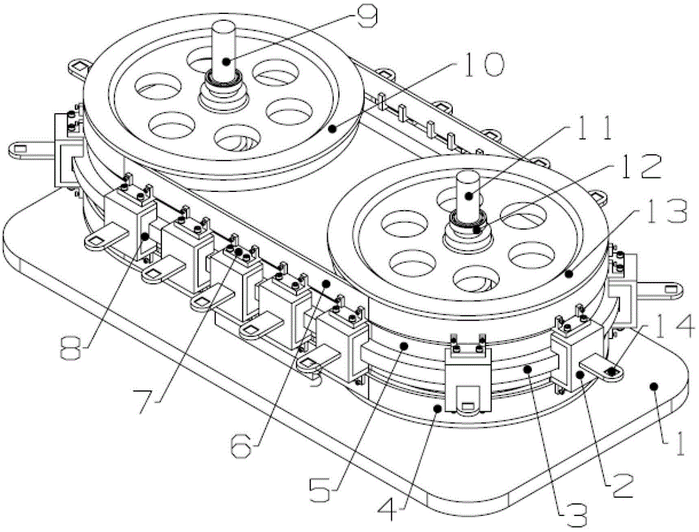
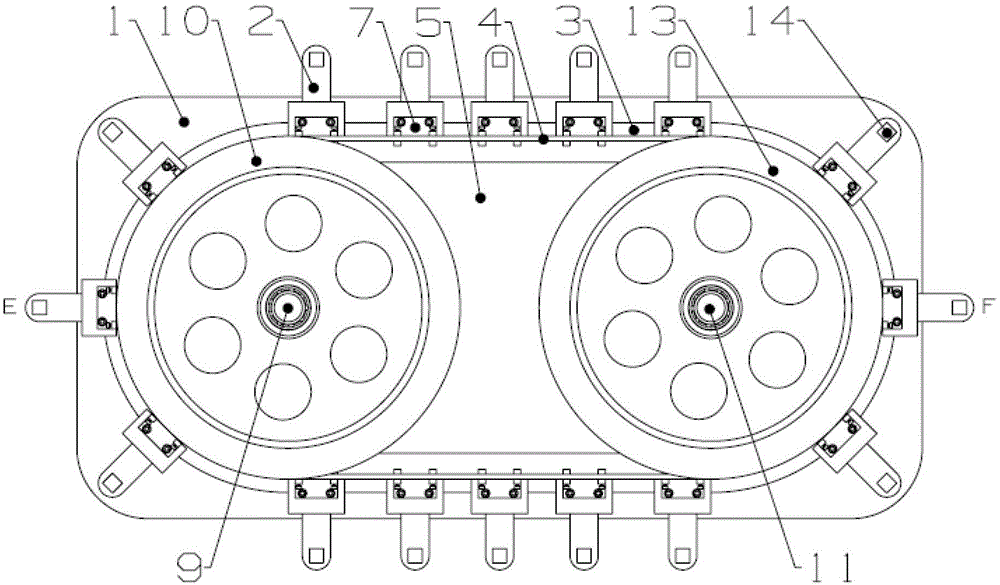
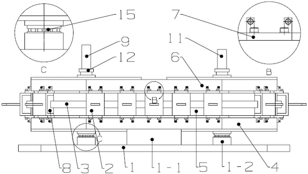
[0027] like Figure 1~4 As shown, the double-sided drive ring guide rail chip transfer device of the present invention includes a base 1, and a synchronous transmission mechanism, a ring guide rail sliding mechanism and a loading mechanism arranged on the base 1, wherein:

[0028] The base 1 has a support frame 1-1 and two bosses 1-2, and the two bosses 1-2 are located on both sides of the support frame 1-1 and symmetrical to the center of the support frame 1-1.

[0029] The synchronous transmission mechanism includes a driving shaft 11 and a driven shaft 9, and the lower ends of the driving shaft 11 and the driven shaft 9 are respectively installed on two bosses 1-2 on the base 1 using one-way thrust ball bearings 15, The upper driving synchronous pulley 13 and the lower driving synchronous pulley 17 are fixed coaxially on the driving shaft 11 from top to bottom, and the upper driven synchronous pulley 10 is coaxially fixed on the driven shaft 9 from top to bottom. and the l...


PUM


Abstract

The invention discloses a bilateral driving type annular guide rail chip transmission device which comprises a base, a synchronous transmission mechanism, an annular guide rail sliding mechanism and a material carrying mechanism, wherein the synchronous transmission mechanism, the annular guide rail sliding mechanism and the material carrying mechanism are arranged on the base. The synchronous transmission mechanism adopts an upper transmission mechanism and a lower transmission mechanism for synchronous driving, wherein the upper transmission mechanism is formed by an upper driving synchronous pulley, an upper driven synchronous pulley and an upper synchronous driving belt, and the lower transmission mechanism is formed by a lower driving synchronous pulley, a lower driven synchronous pulley and a lower synchronous driving belt. The annular guide rail sliding mechanism comprises a guide rail support arranged between the upper synchronous transmission belt and the lower synchronous transmission belt, an annular guide rail installed on the guide rail support and a plurality of sliders in sliding match with the annular guide rail. The material carrying mechanism comprises a material carrying block fixed on the sliders and used for carrying materials, two ends of the material carrying block are respectively connected onto the upper transmission mechanism and the lower transmission mechanism. The bilateral driving type annular guide rail chip transmission device is simple in structure, small in mechanical vibration and accurate and smooth in transmission.

Description

technical field [0001] The invention relates to a material conveying device, in particular to a double-sided drive ring guide rail chip conveying device used for conveying chips in integrated circuit packaging equipment. Background technique [0002] In the automatic production line, the material transmission device connects the various stations in the production line and acts as a bridge. Nowadays, with the continuous development of integrated circuit manufacturing technology, the automatic production line of integrated circuit manufacturing is developing in the direction of high speed, high precision and high reliability. Since the operation object of the integrated circuit manufacturing line is a chip with a very small feature size, strict requirements are placed on the vibration, fast smoothness and precise emergency stop during the transmission device. In the existing material conveying devices of integrated circuit packaging equipment, belt transportation, chain plate...

Claims


Application Information

Patent Timeline
IPC IPC(8): B65G17/12B65G23/00B65G21/22
Inventor 黄美发邱彪肖萌萌胡汝凯莫保锋肖威
Owner GUILIN UNIV OF ELECTRONIC TECH
Why Eureka
Try Eureka