A current conversion device for an automatic phase separation system on the ground of an electrified railway

An automatic over-phase, electrified railway technology, applied in output power conversion devices, AC networks with different sources of the same frequency, power lines, etc., can solve over-voltage and over-current surge, high over-voltage and over-current surge , mechanical switch switching time is long and other problems, to achieve the effect of continuous power supply

Active Publication Date: 2020-02-04
中国船舶重工集团公司第七一二研究所 +2
View PDF5 Cites 0 Cited by
  • Summary
  • Abstract
  • Description
  • Claims
  • Application Information

AI Technical Summary

Problems solved by technology

[0005] Over-phase splitting equipment based on automatic switching of ground mechanical switches has a small amount of application in my country, but the actual application also shows the following defects: 1) Mechanical switch switching cannot accurately control the phase, and there are overvoltage and overcurrent impacts; 2) Mechanical switches The switching time is long, and there is a long non-electric dead zone in the neutral section during the commutation process; 3) There is a high overvoltage and overcurrent impact, and the control software and protection setting value of the train need to be modified; 4) The life of the mechanical switch is low , requires regular maintenance and replacement, high operating costs in the later period
[0006] In view of some defects in the automatic switching over-phase separation technology of ground mechanical switches, in recent years, relevant institutions have also carried out research on automatic switching over-phase separation technology based on ground electronic switches. This technology is characterized by the use of electronic switches instead of mechanical switches. The basic principle of over-phase separation has not changed, so there must still be an electric dead zone in the neutral section during the commutation process, which will still bring problems such as overvoltage and overcurrent shocks to the train

Method used


Image

  • A current conversion device for an automatic phase separation system on the ground of an electrified railway
  • A current conversion device for an automatic phase separation system on the ground of an electrified railway
  • A current conversion device for an automatic phase separation system on the ground of an electrified railway

Examples


Embodiment Construction

[0027] In order to make the purpose, technical solutions and advantages of the embodiments of the present invention clearer, the technical solutions in the embodiments of the present invention will be clearly described below in conjunction with the accompanying drawings in the embodiments of the present invention. Obviously, the described embodiments are the Some, but not all, embodiments are invented. Based on the embodiments of the present invention, all other embodiments obtained by persons of ordinary skill in the art without making creative efforts belong to the protection scope of the present invention.

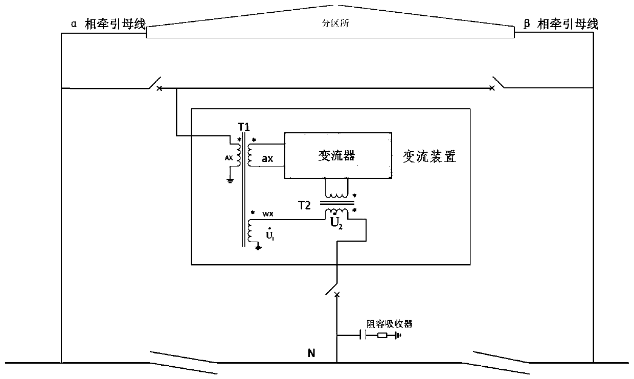
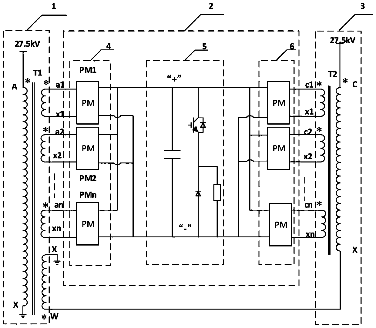
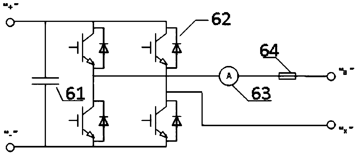
[0028] The embodiment of the present invention proposes a converter device for an automatic phase separation system on the ground of an electrified railway. Compared with other automatic phase separation technologies mentioned in the background art, an advanced power electronic converter device and a special transformer are used as the core The component realizes the sm...


PUM


Abstract

The invention provides a converter device of an electric railway ground auto-passing neutral section system. The device comprises a rectifier side single-phase multi-winding rectifier transformer T1,an inverter single-phase multi-winding inverter transformer T2 and a back-to-back four-quadrant converter; the device is used for conducting AC-DC-AC transformation on accessed alpha-phase and beta-phase traction busbar power supply, and supplying electricity to a catenary electricity sub-phase neutral section; a high-voltage winding is arranged on the T1 primary side, and n low-voltage windings and one high-voltage winding are arranged on the secondary side; n low-voltage windings are arranged on the T2 primary side, and one high-voltage winding is arranged on the secondary side; the secondary side high-voltage winding is connected with the secondary side high-voltage winding in series to be combined into voltage to supply electricity to the neutral section. Accordingly, the advanced power electronic converter device and a special transformer serve as core components, continuous power supply of the catenary electricity sub-phase neutral section can be achieved, a train can avoid powerfailure for the passing neutral section, no electric arc or overvoltage can be generated.

Description

technical field [0001] The invention relates to the technical field of railway power supply, in particular to a current conversion device for an automatic phase separation system on the ground of an electrified railway. Background technique [0002] my country's electrified railway traction network adopts phase-separated and segmented single-phase power frequency AC power supply, and there are about 200-900m of electric split-phase with neutral section every 30-60km. Under the condition of three-phase transformer power supply, the partition is located The design phases of the catenary on both sides of the split phase are the same, but they are powered by feeders from different substations, so the phase difference is small; in addition, different voltage isolation is set between the catenary systems fed by different feeders from the bus of the same substation. Electrically segmented joints that function as electrical split phases, these are called virtual electrical split phase...

Claims


Application Information

Patent Timeline
Patent Type & Authority Patents(China)
IPC IPC(8): H02M5/458H02J3/06B60M3/04
CPCB60M3/04H02J3/06H02M5/458
Inventor 方华松邱长青许晓辉戚广枫李红梅张新民高晓峰石媛刘聪杨帆
Owner 中国船舶重工集团公司第七一二研究所
Why Eureka
Try Eureka