

Starting control system and starting control method for combustible gas detector
A gas detector and start-up control technology, which is applied in the direction of instruments and alarms, can solve the problems of increasing the cost of the alarm system, large start-up current, waste of resources, etc., and achieve the effects of reducing reliability, avoiding waste, and improving efficiency
Active Publication Date: 2016-10-12
BAIYI LIGHTING (SHANGHAI) HLDG LTD
View PDF5 Cites 0 Cited by
- Summary
- Abstract
- Description
- Claims
- Application Information
AI Technical Summary
Problems solved by technology
[0003] The existing combustible gas detectors generally have a working current of about 30mA and a rated voltage of 24V, but the starting current is relatively large, about 100-120mA
And the duration is 2 to 3 seconds, so the power supply for combustible gas detectors can generally only be designed according to the size of the starting current
For example, a power supply with a rated cu
Method used
View moreImage
Smart ImageViewing Examples

Examples
 PUM
 Abstract
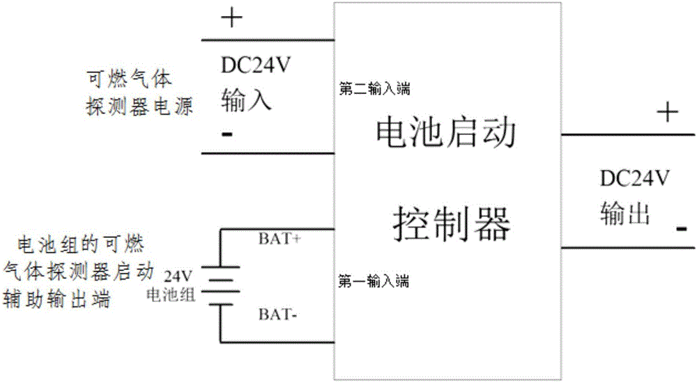
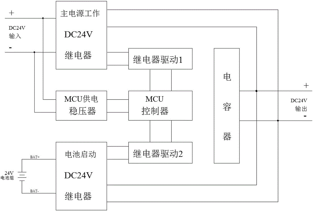
The present invention relates to a starting control system for a combustible gas detector. The system comprises a control cabinet, and a combustible gas controller and a battery pack are arranged inside the control cabinet. The battery pack is provided with a combustible gas controller output end and a combustible gas detector starting auxiliary output end. The combustible gas controller output end is connected with a combustible gas controller. The combustible gas detector starting auxiliary output end of the battery pack is connected with the first input end of a battery starting controller. The main power supply output end of the combustible gas detector is connected with the second input end of the battery starting controller. The output end of the battery starting controller is connected with the gas detector. When the gas detector is started, only the combustible gas detector starting auxiliary output end of the battery pack powers on the battery starting controller. After the starting process of the gas detector, only the main power supply output end of the combustible gas detector powers on the battery starting controller. The starting control system for the combustible gas detector can be applied to a combustible gas detection and alarm system.
Description
technical field [0001] The invention relates to a gas alarm system, in particular to a combustible gas detector start-up control system used in the gas alarm system, and belongs to the technical field of combustible gas detector start-up control. Background technique [0002] The combustible gas detection and alarm system is an independent subsystem of the automatic fire alarm system, which belongs to the fire early warning system and can be composed of combustible gas controllers, combustible gas detectors and fire sound and light alarms. When the alarm signal of combustible gas needs to be connected to the automatic fire alarm system, it is generally connected by the combustible gas controller. [0003] In the existing combustible gas detectors, the operating current is generally about 30mA, and the rated voltage is generally 24V, but the starting current is relatively large, about 100-120mA. And the duration is 2 to 3 seconds. Generally, the power supply for combustible ...
Claims
Login to View More Application Information
Patent Timeline
 IPC IPC(8): G08B21/16
CPCG08B21/16
Inventor谢文学
OwnerBAIYI LIGHTING (SHANGHAI) HLDG LTD