Continuous progressive die for waisted type cooling fin

A heat sink and progressive technology, which is applied in the field of waist-type heat sink continuous progressive die, can solve the problems of low production efficiency, imperfect punch structure design, inability to achieve continuous production, etc., to ensure accuracy and effectiveness. performance, prolonging structural strength and service life

Pending Publication Date: 2018-05-22
SHENZHEN JINZHOU PRECISION TECH
View PDF0 Cites 0 Cited by
  • Summary
  • Abstract
  • Description
  • Claims
  • Application Information

AI Technical Summary

Problems solved by technology

[0003] The purpose of the present invention is to provide a continuous progressive mold for waist-retracting fins, aiming to solve the problem that the existing m

Method used


Image

  • Continuous progressive die for waisted type cooling fin
  • Continuous progressive die for waisted type cooling fin
  • Continuous progressive die for waisted type cooling fin

Examples


Embodiment Construction

[0021] In order to make the object, technical solution and advantages of the present invention clearer, the present invention will be further described in detail below in conjunction with the accompanying drawings and embodiments. It should be understood that the specific embodiments described here are only used to explain the present invention, not to limit the present invention.

[0022] It should be noted that when an element is referred to as being “fixed” or “disposed on” another element, it may be directly on the other element or be indirectly on the other element. When an element is referred to as being "connected to" another element, it can be directly connected to the other element or indirectly connected to the other element.

[0023] It is to be understood that the terms "length", "width", "top", "bottom", "front", "rear", "left", "right", "vertical", "horizontal", "top" , "bottom", "inner", "outer" and other indicated orientations or positional relationships are b...


PUM


Abstract

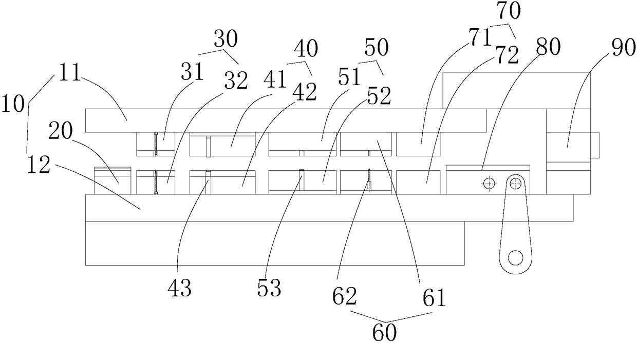
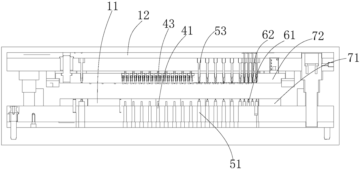
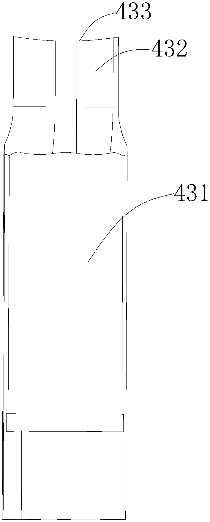
The invention belongs to the technical field of die structures, and provides a continuous progressive die for a waisted type cooling fin. The continuous progressive die comprises a die hold assembly,a feeding assembly, a punching assembly, a flanging guide assembly and a discharging assembly, wherein the feeding assembly, the punching assembly and the flanging guide assembly are sequentially arranged in the length direction of the die holder assembly; the die holder assembly comprises a first die assembly and a second die assembly which are oppositely arranged; the punching assembly comprisespunching female die bodies and first punch parts, wherein the female die bodies are arranged on the first die assembly, and the first punch parts are connected to the second die assembly; the flanging guide assembly comprises flanging female die bodies and second punch parts, wherein the flanging female die bodies are arranged on the first die assembly, and the second punch parts are used for flanging openings punched by the punch parts; the first punch parts are in the shape of a ladder; the front end surfaces of the first punch parts are arc-shaped; and guide parts are further arranged at the front end parts of the second punch parts. The continuous progressive die has the advantage that by means of the design, the problems that an existing die structure cannot realize continuous production, and meanwhile, the production efficiency is low due to the fact that the design of a punch structure is incomplete can be solved.

Description

technical field [0001] The invention belongs to the technical field of mold structures, and in particular relates to a waist-retracting heat sink continuous progressive mold. Background technique [0002] The waist heat sink is the core part of the car air conditioner. The car air conditioner factory developed the waist heat sink in order to improve the cooling effect of the air conditioner. The waisted heat sink is used for the core parts of the car air conditioner, and the thickness of the single heat sink is only 0.07mm, the width is 16mm or 24mm, and the length is in the range of 300-500mm. The maximum stamping speed of the mold can reach 250 times / min , The punch and die gap is 0.005mm. Furthermore, the mold requirements for the production of heat sinks are relatively high. The traditional mold structure punch structure is not strong enough, and the hole pattern after punching is unstable, which makes it difficult to stack heat sinks and install flat tubes. In addition...

Claims


Application Information

Patent Timeline
IPC IPC(8): B21D37/08
CPCB21D37/08
Inventor 朱建敏林鹏唐永红唐典
Owner SHENZHEN JINZHOU PRECISION TECH
Why Eureka
Try Eureka