Spherical display structure and CAVE system with same

A display structure, spherical structure technology, applied in the direction of instruments, identification devices, etc., can solve the problem of poor display effect of the display system

Pending Publication Date: 2018-05-22
BEIJING LIYADE EQUIP TECH CO LTD
View PDF0 Cites 11 Cited by
  • Summary
  • Abstract
  • Description
  • Claims
  • Application Information

AI Technical Summary

Problems solved by technology

[0007] The main purpose of the present invention is to provide a spherical display structure and its CAVE system to solve the problem of poor display effect of the display system in the prior art

Method used


Image

  • Spherical display structure and CAVE system with same
  • Spherical display structure and CAVE system with same
  • Spherical display structure and CAVE system with same

Examples


Embodiment Construction

[0030] It should be noted that, in the case of no conflict, the embodiments in the present application and the features in the embodiments can be combined with each other. The present invention will be described in detail below with reference to the accompanying drawings and examples.

[0031] It should be noted that the terminology used here is only for describing specific implementations, and is not intended to limit the exemplary implementations according to the present application. As used herein, unless the context clearly dictates otherwise, the singular is intended to include the plural, and it should also be understood that when the terms "comprising" and / or "comprising" are used in this specification, they mean There are features, steps, operations, means, components and / or combinations thereof.

[0032] It should be noted that the terms "first" and "second" in the specification, claims and drawings of the present application are used to distinguish similar objects, ...


PUM


Abstract

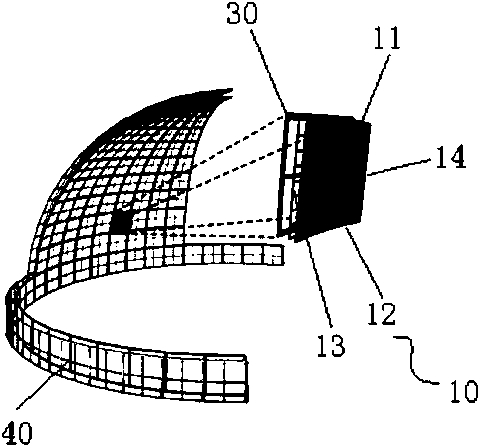
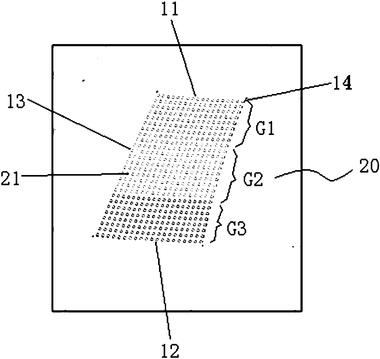
The invention provides a spherical display structure and a CAVE system with the same. The spherical display structure includes a plurality of light board units, the light board units are spliced to form a spherical structure. The upper side edge of each light board unit along the weft direction of the spherical structure and the lower side edge arranged opposite to the upper side edge are both ofan arc structure, and the length of each upper side edge is not equal to the length of the corresponding lower side edge. The upper side edge of one light board unit of every two light board units arranged adjacently in the weft direction is arranged adjacent to the lower side edge of the other light board unit. Since the light board units adopt the structure above, the light board units are arbitrarily spliced and combined at integer multiples of X degrees in the horizontal viewing angle and arbitrarily spliced and combined at integer multiples of Y degrees in the vertical viewing angle to form the display structure in a spherical shape. Through the arrangement, the display effect of the display structure can be effectively improved.

Description

technical field [0001] The present invention relates to the technical field of display systems, in particular to a spherical display structure and a CAVE system having the same. Background technique [0002] Because the CAVE system can provide a simulation environment with a large field of view, heavy immersion, and high fidelity, it has been highly valued by the simulation field since its birth. In 1992, the EVL Laboratory of Illinois State University in the United States designed the first CAVE system, which used 4 SGI workstations to generate 120Hz stereoscopic images synchronously, and used 4 projectors to display them on the screen. For a while, the CAVE system user community was limited to research institutions. [0003] With the rapid development of information technology, the application range of CAVE system is more and more extensive, and its technical form has also changed. From the perspective of display (screen) splicing, it includes two or more plane splicing,...

Claims


Application Information

Patent Timeline
Patent Type & Authority Applications(China)
IPC IPC(8): G09F9/33
CPCG09F9/33
Inventor 谯谊魏洪亮詹培青张龙虎谢光明孙雪超毕洪哲
Owner BEIJING LIYADE EQUIP TECH CO LTD
Why Eureka
Try Eureka