Rolling bearing device

A technology of rolling bearings, bearing parts, applied in the direction of ball bearings, shafts and bearings, bearing components, etc., which can solve the problems of lubricating oil consumption, impossibility of allowing the oil supply unit 100 to function, and increased frequency of maintenance

Inactive Publication Date: 2021-03-02
JTEKT CORP
View PDF1 Cites 0 Cited by
  • Summary
  • Abstract
  • Description
  • Claims
  • Application Information

AI Technical Summary

Problems solved by technology

In this case, even when the oil droplet P is caused to fly out of the pump 90, there is a possibility that the oil droplet P does not reach the desired part (the ball 98) due to the influence of the flow of the rotating air.
As a result, lubricating oil is uselessly consumed, and thus it is impossible to allow the oil supply unit 100 to function for a long period of time
Therefore, the frequency of maintenance increases, and, for example, in the case of machine tools, production efficiency is lowered

Method used


Image

  • Rolling bearing device
  • Rolling bearing device
  • Rolling bearing device

Examples


Embodiment Construction

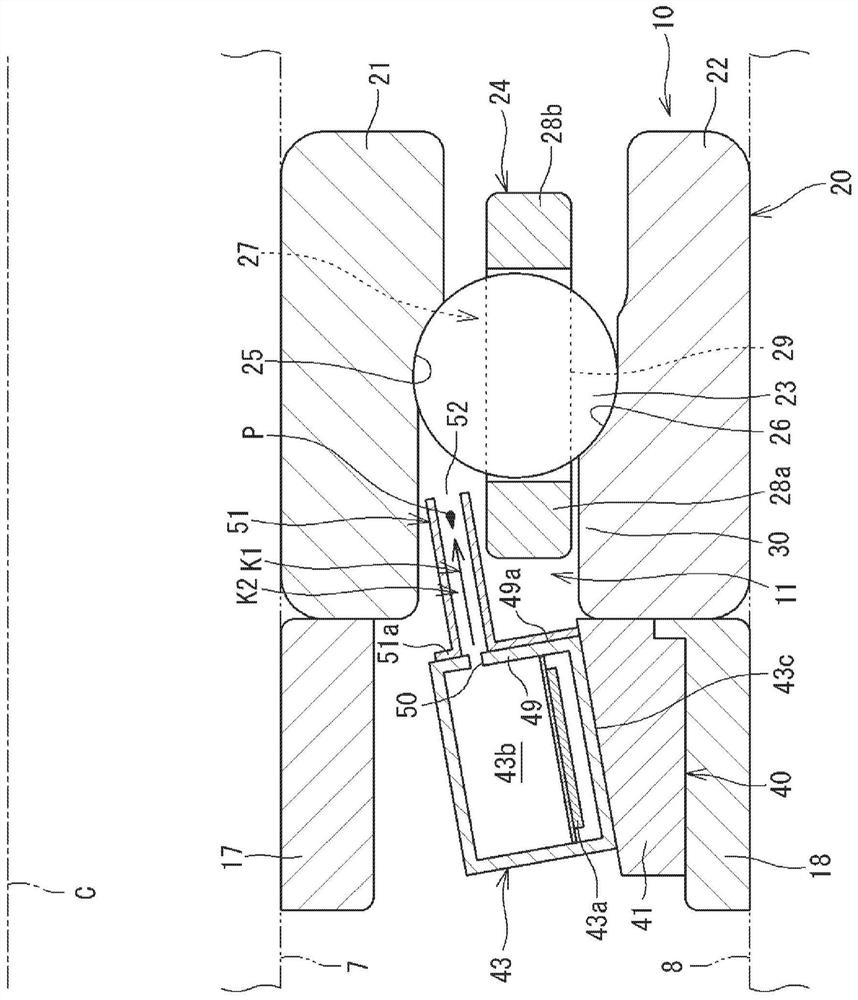
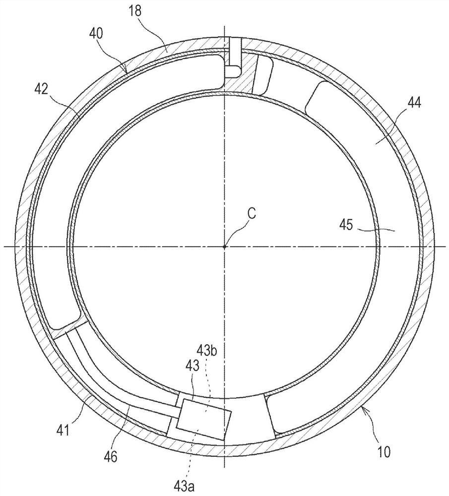
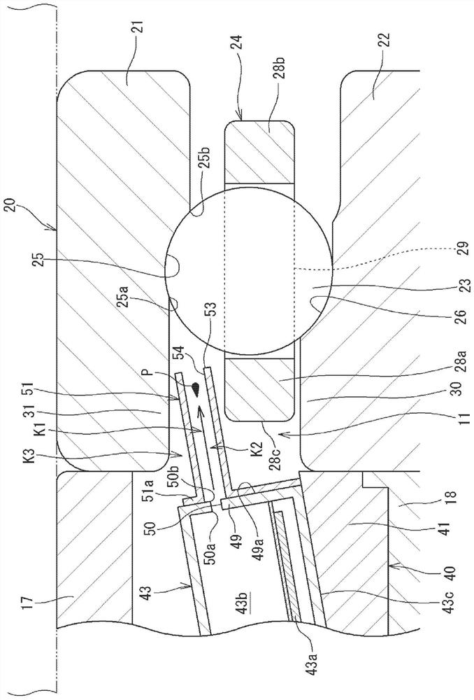
[0022] figure 1 is a sectional view showing the rolling bearing device according to the embodiment. figure 1 A rolling bearing device 10 shown in (hereinafter also referred to as "bearing device 10") supports a main shaft 7 of a main shaft device of a machine tool such that the main shaft 7 is rotatable. The bearing arrangement 10 is housed in the bearing housing 8 of the spindle arrangement. exist figure 1 In , the main shaft 7 and the bearing housing 8 are shown by double-dashed lines. The bearing device 10 is also applicable to devices other than machine tools. In the following description, a direction parallel to the center line C of the bearing device 10 is referred to as an "axial direction", and a direction perpendicular to the axial direction is referred to as a "radial direction".

[0023] The bearing device 10 includes a bearing portion 20 and an oil supply unit 40 . This bearing unit 20 includes an inner ring 21 , an outer ring 22 , a plurality of balls (rol...


PUM


Abstract

The invention relates to a rolling bearing device comprising a bearing portion (20) having an inner ring (21), an outer ring (22), a plurality of rolling elements (23) which are arranged between the inner ring (21) and the outer ring (22), and a cage (24) holding the plurality of rolling elements (23); and an oil supply unit (40) disposed adjacent to the bearing portion (20) in an axial directionand including a pump (43) having an injection port (50) from which lubricating oil is injected as an oil drop into the bearing portion (20). The oil supply unit (40) further includes a wind shieldingportion (51) surrounding a passage area through which the oil drop injected from the injection port (50) passes, the wind shielding portion (51) is provided with no clearance between the wind shielding portion (51) and the pump (43 ) in which the injection port (50) opens, and the wind shielding portion (51) is opened toward a target in the bearing portion (20).

Description

technical field [0001] The invention relates to a rolling bearing device comprising a bearing part and an oil supply unit arranged adjacent to the bearing part in the axial direction. Background technique [0002] In recent years, in various machine tools, in order to improve machining efficiency and production efficiency, an increase in the rotational speed of the spindle has been required. When the main shaft rotates at high speed, especially, lubrication in a bearing portion supporting the main shaft is important. Therefore, there has been proposed a rolling bearing device in which an oil supply unit is provided adjacent to a bearing portion in the axial direction (see Japanese Patent Application Laid-Open No. 2004-108388 (JP2004-108388A)). The oil supply unit includes a tank for storing lubricating oil, a pump for supplying the lubricating oil in the tank to the bearing portion, and the like. [0003] In the above rolling bearing device, since the tank storing lubricat...

Claims


Application Information

Patent Timeline
Patent Type & Authority Patents(China)
IPC IPC(8): F16C33/66F16C33/58
CPCF16C33/58F16C33/6637F16C19/06F16C33/586F16C33/664F16C33/6659F16C2322/39
Inventor 松山博树山川和芳白井良昌间野洋嗣原田昌宽
Owner JTEKT CORP
Why Eureka
Try Eureka