Control device of electric vehicle with fixed-position automatic stop control mechanism

An automatic stop and control device technology, which is applied in the direction of automatic start device, vehicle control route device, brake action start device, etc., can solve the problem of taking braking characteristics into consideration, so as to avoid useless consumption of kinetic energy, improve regeneration rate, and reduce consumption Reduced effect

Active Publication Date: 2012-06-06
HITACHI LTD
View PDF5 Cites 0 Cited by
  • Summary
  • Abstract
  • Description
  • Claims
  • Application Information

AI Technical Summary

Problems solved by technology

[0005] However, the current fixed-position automatic stop control does not take such braking characteristics into consideration, so the constant braking deceleration control that requires a constant braking force from the high-speed region as described above is performed.
Thus, with Figure 13 The part shown in A corresponds to the amount of kinetic energy that is uselessly consumed by air brakes, etc.

Method used


Image

  • Control device of electric vehicle with fixed-position automatic stop control mechanism
  • Control device of electric vehicle with fixed-position automatic stop control mechanism
  • Control device of electric vehicle with fixed-position automatic stop control mechanism

Examples


Embodiment Construction

[0052] Hereinafter, embodiments of the present invention will be described with reference to the drawings.

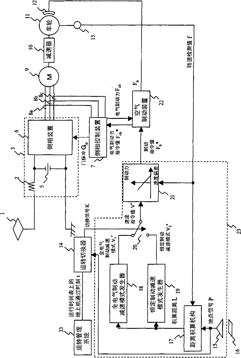
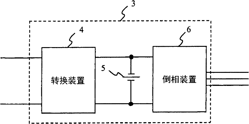
[0053] First, use figure 1 , taking a DC vehicle as an example to illustrate an embodiment of the present invention. As shown in the figure, a power collector 1 and an inverter 6 electrically connected to a trolley line are connected via a filter reactor 2 . The smoothing capacitor 5 is connected to the input side of the inverter device 6 , and the main motor 9 is connected to the output side of the inverter device 6 . The power conversion device 3 is composed of a filter reactor 2 , an inverter device 6 and a filter capacitor 5 . In addition, current detectors 8 a , 8 b , 8 c for detecting motor current flowing from inverter device 6 to main motor 9 , speed reducer 10 , and rotation speed detector 13 for detecting rotation speed of wheels 11 are provided. The rotational speed detector 13 sends the detected rotational speed detection value f to the distance accumula...


PUM


Abstract

The invention relates to a control device of an electric vehicle. In a fixed-position automatic stop control mechanism, the vehicle stops at a target position through a constant deceleration mode of a constant braking force generated by combined reclamation braking and air braking, therefore energy of the vehicle is consumed invalidly because of air braking. Aiming at the problem, the technical scheme of the control device of the electric vehicle is that, the fixed-position automatic stop control mechanism of the control device of the electric vehicle is pre-provided with an all-electric braking deceleration mode that can decelerate in a range of the braking force reclaimed by electric power of a main motor. The vehicle stops at the target position according to the all-electric braking deceleration mode. Fixed-position automatic stop is carried out by regenerative braking, thus consumption inutile of energy because of air braking is avoided, and then frequency of utilization of air braking is reduced, so that abrasion of brake shoes is inhabited.

Description

technical field [0001] The invention relates to a fixed-position automatic stop control device for a railway vehicle, and relates to a control device for an electric vehicle with a fixed-position automatic stop control mechanism. Background technique [0002] Fixed-position automatic stop control technology for the purpose of automatically stopping a vehicle at a fixed position is known. Fixed-position automatic stop control is a control that automatically controls the braking force of the vehicle to automatically stop the vehicle at a stop target point (such as a stop point at a station). There are following schemes as the method that the fixed position of the vehicle is automatically stopped: as Figure 10 As shown, a location signal transmitter (ground device) is installed at a predetermined point in front of the stopping point, which is detected by the antenna (vehicle device) and the location signal detection device mounted on the vehicle. Figure 10 The stop point show...

Claims


Application Information

Patent Timeline
Patent Type & Authority Patents(China)
IPC IPC(8): B60L7/00B60L15/20
CPCY02T10/7258B60L7/26B60L2200/26B60T1/10B60L7/14B60L15/2009B60T7/18B60T7/22Y02T10/64Y02T10/72B60T7/128B60L7/00B61L3/08
Inventor 大石亨一丰田瑛一
Owner HITACHI LTD
Why Eureka
Try Eureka