
Design method and grounding grid of converter station grounding grid that can replace DC grounding pole

A grounding grid design, DC grounding technology, applied in the substation grounding layout and other directions, can solve the problem that the grounding pole cannot be put into production as scheduled, hinder the economic and social benefits of large-capacity and long-distance power transmission, and affect the smooth operation of the two-pole DC transmission project. problems, achieve obvious economic and social benefits, and ensure the effect of safety

Active Publication Date: 2020-08-21
CHINA ELECTRIC POWER RES INST +3
View PDF4 Cites 0 Cited by
  • Summary
  • Abstract
  • Description
  • Claims
  • Application Information

AI Technical Summary

Problems solved by technology

In the actual project construction and construction process, due to external reasons such as land acquisition and site selection, the ground electrode cannot be put into production as scheduled, which affects the smooth commissioning of the bipolar poles of the DC transmission project, and seriously hinders the economic and social benefits of large-capacity and long-distance power transmission.
At present, few scholars, research institutions or equipment manufacturers at home and abroad have carried out research on other grounding devices that can replace DC grounding electrodes, and research on them is undoubtedly forward-looking and practical

Method used


Image

  • Design method and grounding grid of converter station grounding grid that can replace DC grounding pole
  • Design method and grounding grid of converter station grounding grid that can replace DC grounding pole
  • Design method and grounding grid of converter station grounding grid that can replace DC grounding pole

Examples


Embodiment Construction

[0048] The present invention will be further described below in conjunction with the accompanying drawings and specific embodiments, so that those skilled in the art can better understand the present invention and implement it, but the examples given are not intended to limit the present invention.

[0049] The inventor noticed during the invention that:

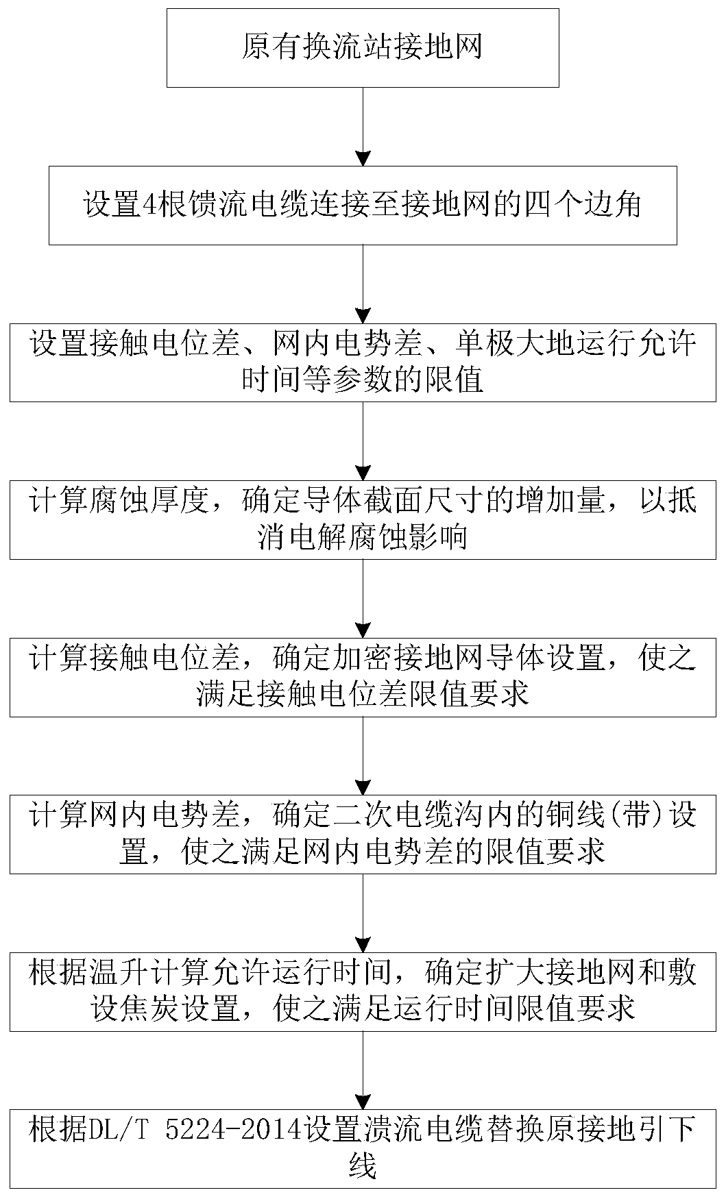
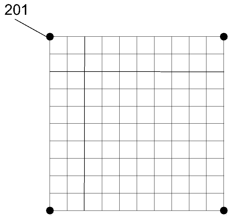
[0050] Although the DC grounding pole has a relatively large current into the ground, the operating time of the single pole of the DC power transmission project is getting shorter and shorter. At present, it is mainly the operation mode that occurs in the case of failure and maintenance. The grounding grid of the converter station is usually established in a place with low soil resistivity, and has the characteristics of large area, large number of conductors, etc., and strong flow capacity. The design method of the grounding grid of the converter station can be studied to make it simultaneously It has the function of flowin...


PUM


Abstract

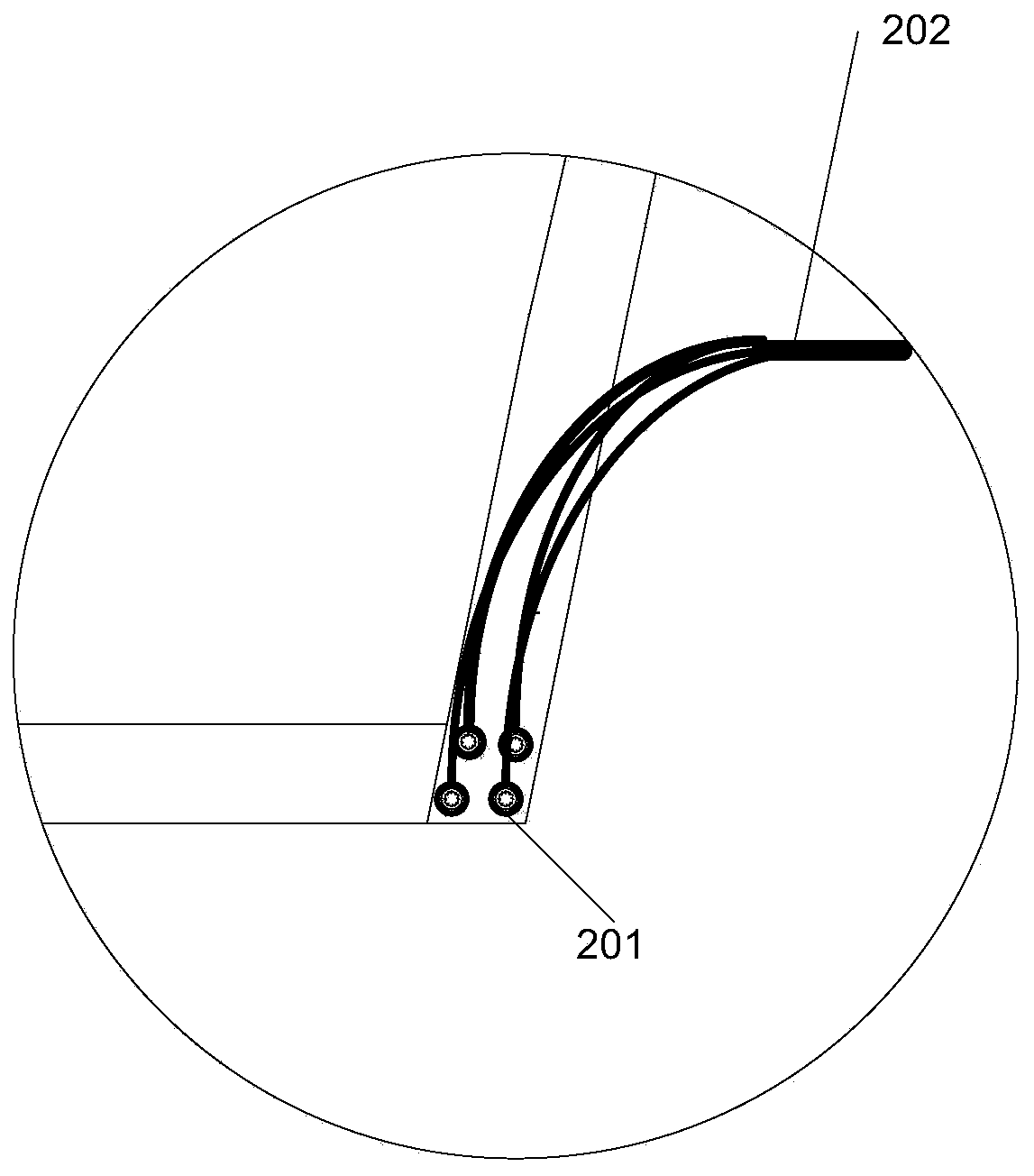
The invention discloses a design method of a converter station ground network capable of being used as a substitute for a DC ground electrode, and the ground network. The design method comprises stepsthat A, a first feeder cable is set to connect from a valve hall ground point to the converter station ground network; B, corrosion thickness of a ground network conductor under the unipolar earth loop current and the bipolar unbalanced current is calculated, and the section size of the ground network conductor is determined; contact potential difference of the ground network is acquired throughcalculation, if the contact potential difference under the DC transmission earth return operating current exceeds a preset contact potential difference limit value, the position of which the contact potential difference exceeds the limit value is added with the ground network conductor, so the contact potential difference decreases to the contact potential difference limit value; and C, a second feeder cable is utilized to connect ground equipment of the converter station ground network with the converter station ground network. The design method is advantaged in that all the functions of a traditional converter station ground network and a DC ground electrode can be realized through an established converter station ground network, the method is safe and reliable, and low cost and high benefit are realized.

Description

technical field [0001] The invention relates to the technical field of direct current transmission, in particular to a design method for a grounding grid of a converter station that can replace a direct current grounding pole, and the grounding grid of a converter station. Background technique [0002] The DC grounding electrode is an important part of the DC transmission project. It serves as a part of the circuit to directly transmit power to the system during unipolar operation, and clamps the neutral point potential of the converter station (rectifier valve) during bipolar operation to avoid the voltage difference between the two poles and the ground. balance and damage the equipment. With the rapid development of UHV DC transmission projects in my country, it is becoming more and more difficult to select the site of DC grounding electrodes. In the actual project construction and construction process, due to external reasons such as land acquisition and site selection, ...

Claims


Application Information

Patent Timeline
Patent Type & Authority Patents(China)
IPC IPC(8): H02B5/01
CPCH02B5/01
Inventor 童雪芳董晓辉谭波谢惠藩潘卓洪王湘汉何慧雯
Owner CHINA ELECTRIC POWER RES INST
Learn More