Network quality monitoring method, device and system

A network quality and proxy server technology, applied in the field of devices and systems, and network quality monitoring methods, can solve problems such as increasing network pressure, and achieve the effects of increasing network pressure, avoiding normal communication, and accurate network quality information.

Active Publication Date: 2018-05-25
云南腾云信息产业有限公司
View PDF6 Cites 16 Cited by
  • Summary
  • Abstract
  • Description
  • Claims
  • Application Information

AI Technical Summary

Problems solved by technology

[0005] In view of this, the present invention provides a network quality monitoring method, device and system to solve the technical problem in the prior art that network pressure will be increased in order to obtain more accurate network quality information

Method used


Image

  • Network quality monitoring method, device and system
  • Network quality monitoring method, device and system
  • Network quality monitoring method, device and system

Examples


Embodiment 1

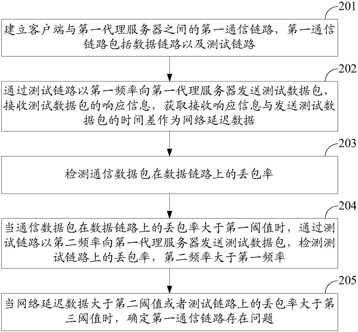
[0035] see figure 2 As shown, the first embodiment of the network quality monitoring method provided in the embodiment of the present invention may include the following steps:

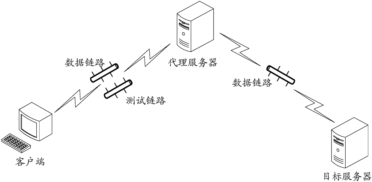
[0036] Step 201: Establish a first communication link between the client and the first proxy server, where the first communication link includes a data link and a test link.

[0037] The first proxy server may be a proxy server currently connected to the client, the communication link between the client and the first proxy server is a first communication link, and the first communication link may include a data link and a test link , the test link is used to transmit test data packets, and the data link is used to transmit normal communication communication data packets.

[0038] Step 202: Send a test data packet to the first proxy server at a first frequency through the test link, receive response information of the test data packet, and acquire the time difference between receiving the response in...

Embodiment 2

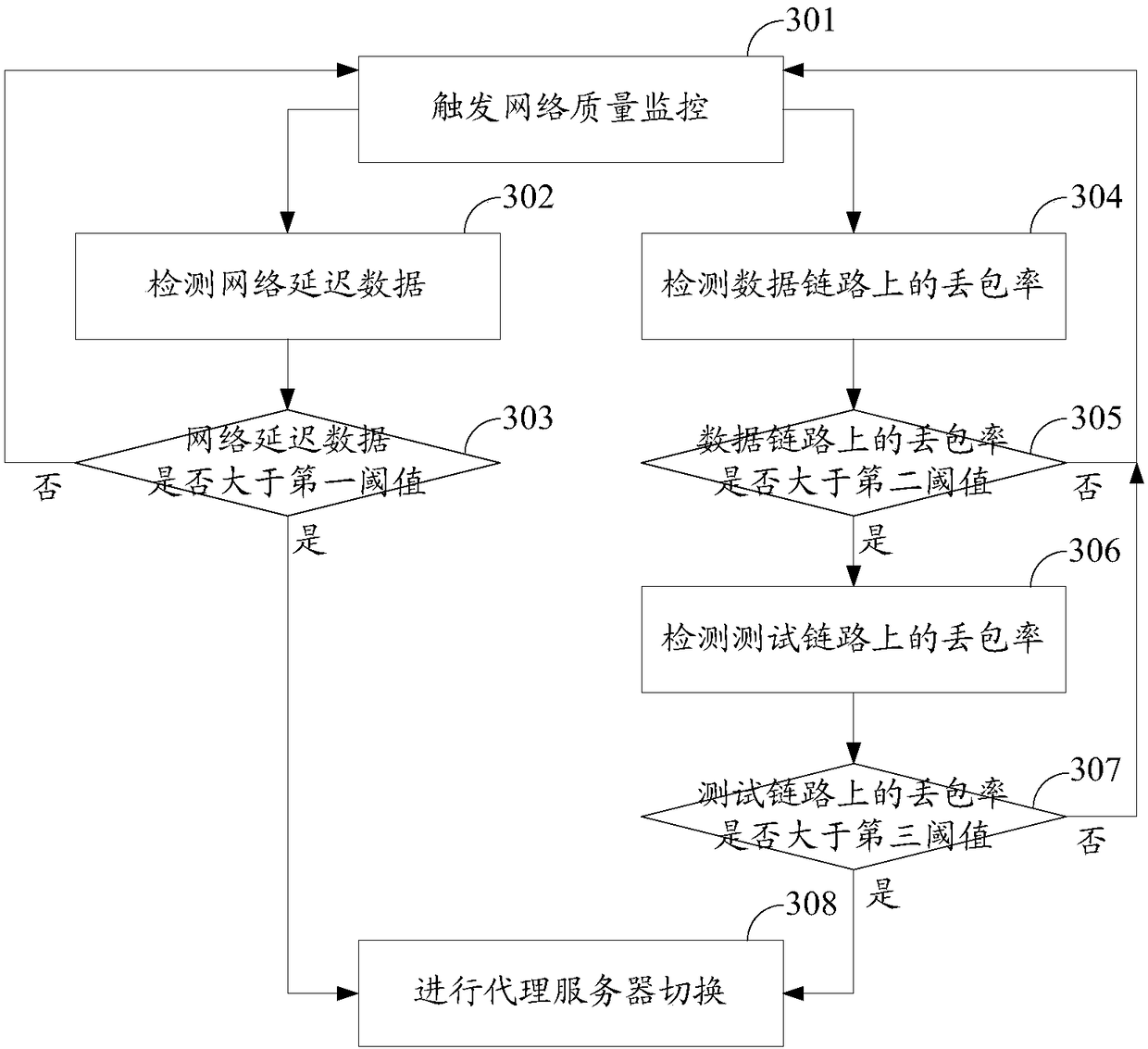
[0060] see image 3 As shown, the second embodiment of the network quality monitoring method provided in the embodiment of the present invention may include the following steps:

[0061] Step 301: Trigger network quality monitoring.

[0062] Step 302: Detect network delay data.

[0063] Step 303: Determine whether the network delay data is greater than the first threshold, if yes, go to step 308, if not, go back to step 301.

[0064] Step 304: Detect the packet loss rate on the data link.

[0065] Step 305: Determine whether the packet loss rate on the data link is greater than the second threshold, if yes, go to step 306, if not, go back to step 301.

[0066] Step 306: Detect the packet loss rate on the test link.

[0067] Step 307: Determine whether the packet loss rate on the test link is greater than the third threshold, if yes, go to step 308, if not, go back to step 301.

[0068] Step 308: Perform proxy server switching.

[0069] In this embodiment, the manners of ...


PUM


Abstract

The invention discloses a network quality monitoring method, device and system, used for performing network quality monitoring in a condition that the network pressure is not increased. The method comprises the steps of: establishing first communication links between a client side and a first proxy server, wherein the first communication links include a data link and a test link; sending a test data packet to the first proxy server at the first frequency through the test link, receiving response information of the test data packet, and obtaining the time difference of the response informationreceiving time and the test data packet sending time as network delay data; detecting the packet loss probability of a communication data packet on the data link; when the packet loss probability of the communication data packet on the data link is greater than a first threshold value, sending the test data packet to the first proxy server at the second frequency through the test link, and detecting the packet loss probability on the test link, wherein the second frequency is greater than the first frequency; and, when the network delay data is greater than a second threshold value or the packet loss probability on the test link is greater than a third threshold value, determining that the first communication links have a problem.

Description

technical field [0001] The invention relates to the technical field of the Internet, in particular to a network quality monitoring method, device and system. Background technique [0002] Currently, a proxy server can be used to relay the communication data packets between the client and the target server, and the network quality of the communication link between the client and the proxy server will affect the communication speed between the client and the target server. [0003] In the prior art, a special test link can be established between the client and the proxy server, and the client uses the test link to regularly send a heartbeat packet to the proxy server to detect whether the link has been disconnected. Based on the data packets, the network delay of the proxy link can be calculated, and the network quality of the proxy link can be judged according to the size of the network delay. It is one-sided to judge the network quality only by the network delay. The client...

Claims


Application Information

Patent Timeline
IPC IPC(8): H04L12/26H04L29/08
CPCH04L43/0829H04L67/56
Inventor 吴广文谢代斌
Owner 云南腾云信息产业有限公司
Why Eureka
Try Eureka