Eureka AIR delivers breakthrough ideas for toughest innovation challenges, trusted by R&D personnel around the world.

Padlock

A padlock and lock body technology, applied in the field of locks, can solve the problems of many internal components, high production costs, and inability to meet the needs of diversified markets, and achieve the effect of compact and simple structure

Inactive Publication Date: 2018-05-29
ZHEJIANG PUJIANG PLUM BLOSSOM LOCK IND GROUP
View PDF6 Cites 0 Cited by
  • Summary
  • Abstract
  • Description
  • Claims
  • Application Information

AI Technical Summary

Problems solved by technology

[0004] However, the structure of the lock cylinder is relatively complex, and there are many internal components, resulting in relatively complicated installation and high production costs; at the same time, the locking and unlocking method is single, which can no longer meet the needs of diversified markets, and cannot realize both mechanical and electrical locking functions

Method used


Image

  • Padlock
  • Padlock
  • Padlock

Examples


Embodiment Construction

[0033] In order to further explain the technical means and effects adopted by the present invention to achieve the intended purpose of the invention, the specific implementation, structure, features and effects of the present invention will be described in detail below in conjunction with the accompanying drawings and preferred embodiments.

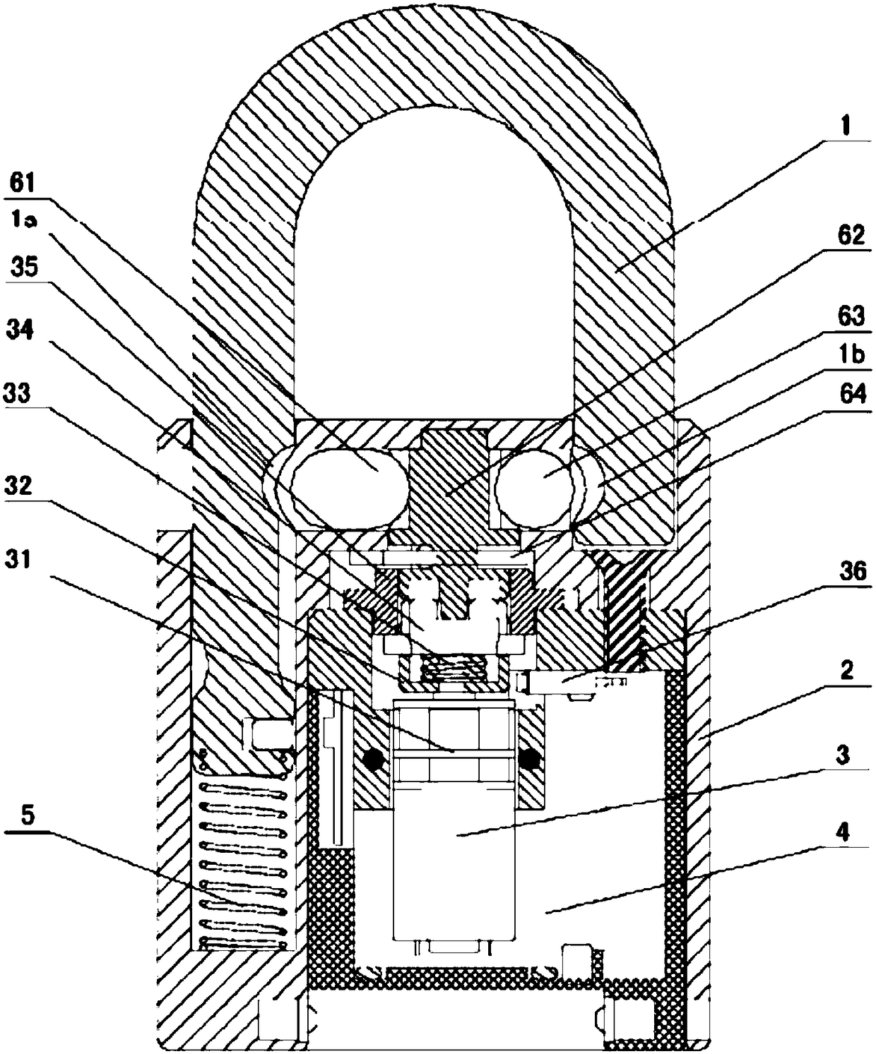
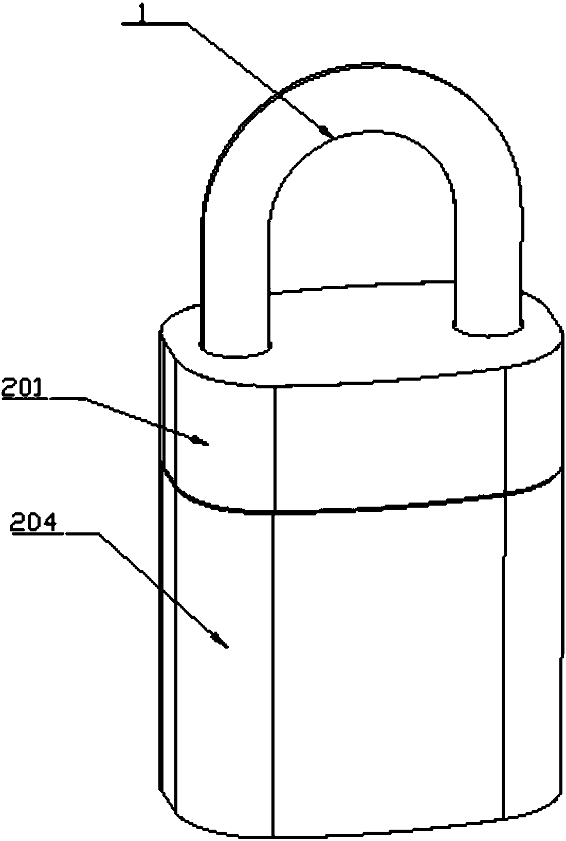
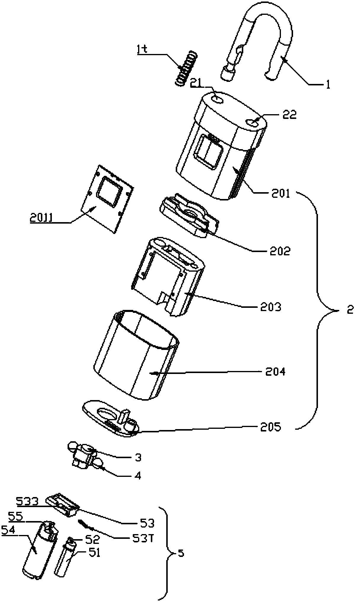
[0034] See figure 2 , 3 , the padlock of the first embodiment of the present invention comprises a U-shaped lock beam 1, a lock body 2, a rotating post 3, a steel ball 4, and a driving mechanism 5. Lock beam 1, lock body 2 realize the locking or unlatching of padlock by cooperating. Rotating column 3, steel ball 4, driving mechanism 5 are all accommodated in the lock body 2.

[0035] The lock beam 1 is provided with a matching depression 10 corresponding to the steel ball 4, and preferably there is a lock beam compression spring 1t between the lock beam 1 and the lock body 2. The lock beam 1 includes a long lock bar 11 , an arc-shaped...


PUM


Abstract

Disclosed is a padlock. The padlock comprises a lock body, a U-shaped ring and a steel ball, wherein the lock ring is provided with a matched groove corresponding to the steel ball. The padlock also comprises a rotating column and a driving mechanism arranged inside the lock body; the rotating column is provided with a protruded part for limiting the steel ball inside the matched groove, and a notch part for providing the steel ball with a space for being released from the matched groove; the driving mechanism is used for driving the rotating column to rotate towards a locking position of thesteel ball from the protruded part as well as towards an unlocking position of the steel ball from the notch part so that the steel ball can be completely separated from the matched groove; the driving mechanism is also used for driving the rotating column to rotate from the unlocking position to the locking position so that the steel ball can be engaged with the matched groove to achieve lockingbetween the lock body and the lock beam. By controlling the protruded part or the notch part of the rotating column to face towards the steel ball, the padlock can achieve locking or unlocking. Also,the padlock is simple and compact in structure.

Description

technical field [0001] The invention relates to the field of locks, in particular to a padlock. Background technique [0002] Traditional mechanical locks and unlocking devices usually use a contact connection structure, which has disadvantages such as low safety, high failure rate, and large functional limitations. Along with the research and development of electronic lockset, it has been generally used in present society. The lock cylinder is the most important component in the lockset, and most of the actions of opening and locking of the lockset are completed through the lock cylinder. [0003] figure 1 Shown is a structural schematic diagram of an existing smart padlock. See figure 1 , the document of authorization announcement number CN205531813U discloses an electronic padlock, including a lock body, a shackle (lock beam) and a lock cylinder assembly, the lock cylinder assembly includes: a locking pinball (hard ball), and the locking pinball is matched with the gr...

Claims


Application Information

Patent Timeline
Patent Type & Authority Applications(China)
IPC IPC(8): E05B67/00
CPCE05B67/00
Inventor 赵卫阳
Owner ZHEJIANG PUJIANG PLUM BLOSSOM LOCK IND GROUP
Why Eureka
Eureka Blog
Learn More