
Floating rotary type water nozzle

A floating and faucet technology, applied in shafts, joints, lift valves, etc., can solve the problems of difficult replacement of accessories, waste of water resources and economic losses, no adjustment allowance, etc., to improve sealing and reduce internal leakage. and the effect of leakage

Active Publication Date: 2018-05-29
ANHUI RONGDA VALVE
View PDF5 Cites 0 Cited by
  • Summary
  • Abstract
  • Description
  • Claims
  • Application Information

AI Technical Summary

Problems solved by technology

[0002] Cold water spouts are derived from pipeline valves (commonly known as "faucets"). There are many styles at home and abroad, but there are currently only two types in terms of internal opening and closing structures and sealing forms. One is "spiral-type faucet". The structure of the faucet is simple, the price is low, there is an appropriate adjustment margin, and the accessories are easy to replace, but the performance of the upper seal is congenitally insufficient, which is called "outside leakage", and the other is "ceramic sheet sealed faucet". The structure of this faucet is complex, the price is high, and there is no adjustment margin. Because its structural parts are fixed in fixed positions and sizes, it is not easy to replace parts. If leakage occurs, the whole faucet must be replaced. Most of its leakage occurs in the inner cavity of the valve body. Breakage of the seal, known as an "inner leak"
Whether it is "outside leakage" or "inside leakage", it brings great troubles to people's life and spirit, and wastes a lot of very precious water resources and economic losses, and the water cleaning method is relatively simple

Method used


Image

  • Floating rotary type water nozzle
  • Floating rotary type water nozzle
  • Floating rotary type water nozzle

Examples


Embodiment Construction

[0018] The following will clearly and completely describe the technical solutions in the embodiments of the present invention with reference to the accompanying drawings in the embodiments of the present invention. Obviously, the described embodiments are only some, not all, embodiments of the present invention. Based on the embodiments of the present invention, all other embodiments obtained by persons of ordinary skill in the art without making creative efforts belong to the protection scope of the present invention.

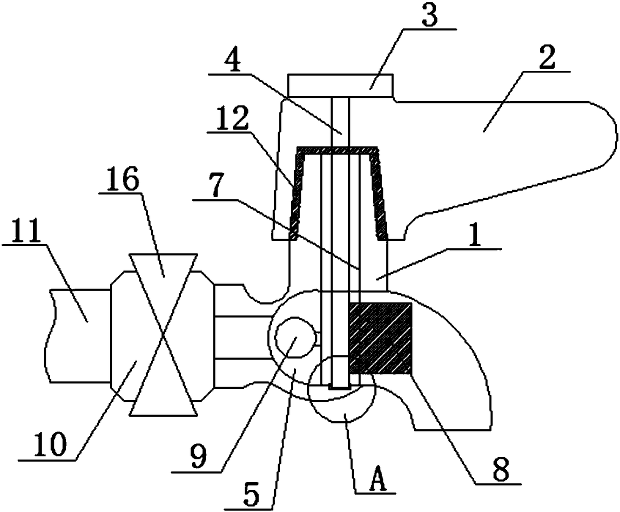
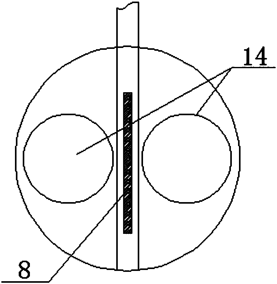
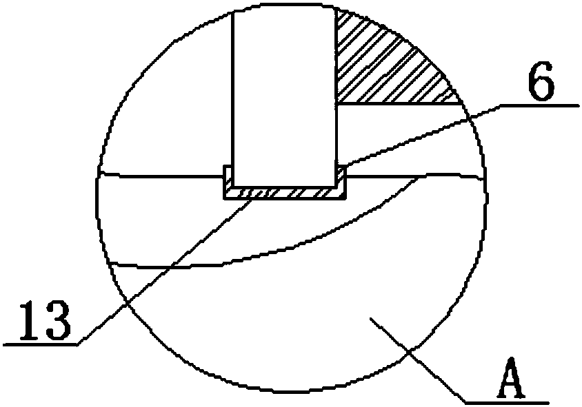
[0019] The present invention provides such Figure 1-5 A floating faucet shown includes a valve body 1, a valve cover 2 is provided on the top of the valve body 1, the valve body 1 is movably connected with the valve cover 2, and an adjustment knob is provided on the top of the valve cover 2 3. The bottom of the adjustment knob 3 is fixed with a first connecting rod 4, the inner cavity of the valve body 1 is provided with a water guide groove 5, and the bottom...


PUM


Abstract

The invention discloses a floating rotary type water nozzle which comprises a valve body. A valve cover is arranged at the top of the valve body. The valve body and the valve cover are movably connected. An adjusting knob is arranged at the top of the valve cover. A first connecting rod is fixedly arranged at the bottom of the adjusting knob. A water guide groove is formed in an inner cavity of the valve body. A groove is formed in the bottom of the water guide groove. The first connecting rod cooperates with the groove. A cover plate is arranged on one side of the first connecting rod. The outer portion of the first connecting rod is sleeved with a second connecting rod. A floating ball plug is fixedly arranged on one side of the second connecting rod. A sleeve is arranged on one side ofthe valve body. When the water nozzle breaks down and needs to be maintained and replaced, a gate valve on the sleeve only needs to be closed, switching of a pipeline main valve is not needed, and thewater utilization condition of a user is prevented from being influenced; the user can select the cleaning manner according to the actual cleaning condition, and convenience and rapidness are achieved; and meanwhile, the conditions of inner leaking and outer leaking can be reduced, and water resources are saved.

Description

technical field [0001] The invention relates to the technical field of pipeline valves, in particular to a floating water nozzle. Background technique [0002] Cold water spouts are derived from pipeline valves (commonly known as "faucets"). There are many styles at home and abroad, but there are currently only two types in terms of internal opening and closing structures and sealing forms. One is "spiral-type faucet". The structure of the faucet is simple, the price is low, there is an appropriate adjustment margin, and the accessories are easy to replace, but the performance of the upper seal is congenitally insufficient, which is called "outside leakage", and the other is "ceramic sheet sealed faucet". The structure of this faucet is complex, the price is high, and there is no adjustment margin. Because its structural parts are fixed in fixed positions and sizes, it is not easy to replace parts. If leakage occurs, the whole faucet must be replaced. Most of its leakage occ...

Claims


Application Information

Patent Timeline
Patent Type & Authority Applications(China)
IPC IPC(8): F16K1/52F16K1/22F16K1/32
CPCF16K1/224F16K1/32F16K1/52F16C2322/59F16C3/02Y10S901/23F16C7/02B25J17/00F16H21/44
Inventor 胡启明
Owner ANHUI RONGDA VALVE
Learn More