Valve braking device and drainage equipment
A technology of braking device and actuating device, applied in valve device, valve operation/release device, mechanical equipment and other directions, can solve the problems of reduced production efficiency and increased production cost, so as to achieve increased production efficiency, reduced production cost, Avoid the effect of personalization
- Summary
- Abstract
- Description
- Claims
- Application Information
AI Technical Summary
Problems solved by technology
Method used
Image

Examples
Embodiment 1
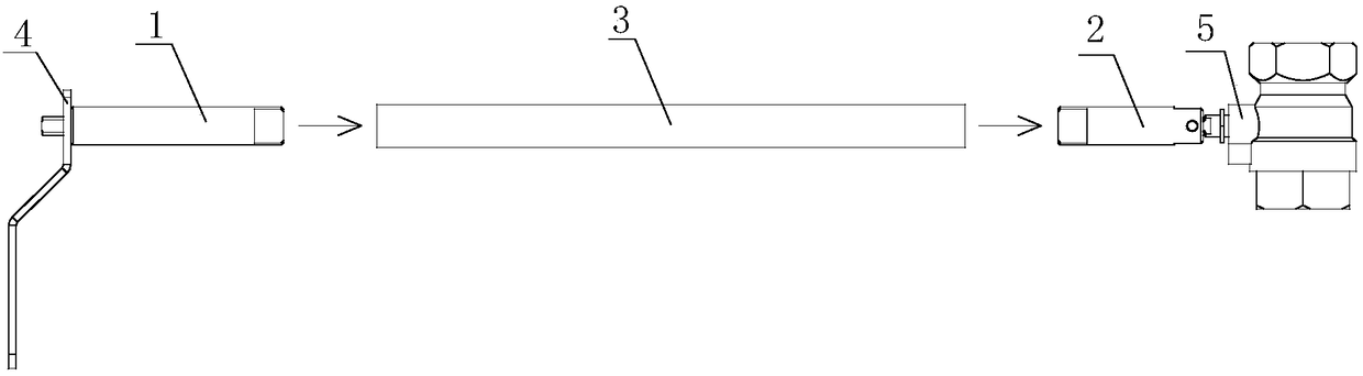
[0047] The valve actuating device of this embodiment includes: a valve actuating member 4 and a follower connecting rod.
[0048] The valve actuator 4 is operatively engaged with the first end of the follower link, the valve stop 4 and the first end of the follower link are fixed at least circumferentially therebetween, upon application of the valve stop 4, The valve stopper 4 rotates around the axis of the follower link, and the valve stopper 4 transmits the received rotational torque to the first end of the follower link.
[0049] The second end of the follower link is operatively engaged with the spool 5 of the valve, and the second end of the follower link and the spool 5 are at least circumferentially fixed. When the rotating torque acts, the follower connecting rod rotates around its own axis, and the follower connecting rod transmits the received rotating torque from the valve braking member 4 to the valve core 5 of the valve.
[0050] The operative engagement of the s...
Embodiment 2
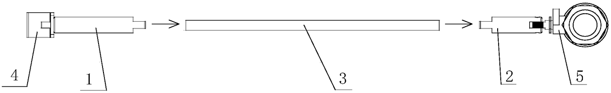
[0074] The difference between the valve braking device of this embodiment and the valve braking device of Embodiment 1 is that the intermediate rod 3 is not integrally formed, but assembled by at least two or more intermediate rod elements extending along the same straight line .
[0075] Specifically, the intermediate rod 3 is composed of at least two or more intermediate rod elements extending along the same straight line, wherein adjacent intermediate rod elements are at least circumferentially fixed. The end surface of one intermediate rod element corresponding to the adjacent other intermediate rod element respectively includes a shape-matched fitting structure.
[0076] When the intermediate rod 3 is composed of two or more intermediate rod elements, the two ends of each intermediate rod element respectively include a first matching structure and a second matching structure, so that using the first matching structure and the second matching The fit of the structures is ...
Embodiment 3
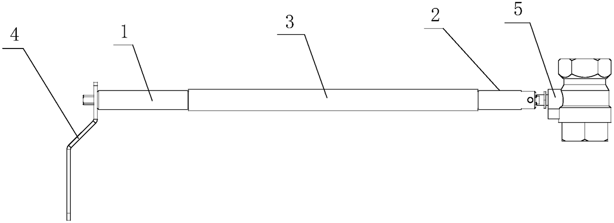
[0079] The difference between the valve brake device in this embodiment and the valve brake device in Embodiment 1 is only that the connection mode between the middle rod 3 and the first rod 1 and the second rod 2 is different.
[0080] Specifically, the middle rod 3 forms an annular hole, the second end of the first rod 1 forms a circular shaft and is provided with a radial hole, and the second end of the first rod 1 connects with the screw passing through the radial hole. At least one wall of the middle rod 3 is connected, the first end of the second rod 2 forms a circular shaft and is provided with a radial hole, and the first end of the second rod 2 is connected to the middle rod by a screw passing through the radial hole. At least one wall of part 3 is connected.
[0081] When the middle rod 3 is a ring hole, the second end of the first rod 1 and the first end of the second rod 2 that cooperate with it form a cylinder, or at least form an outer cylindrical surface, and th...
PUM
 Abstract
Description
Claims
Application Information
 - R&D
- Intellectual Property
- Life Sciences
- Materials
- Tech Scout
- Unparalleled Data Quality
- Higher Quality Content
- 60% Fewer Hallucinations
Browse by: Latest US Patents, China's latest patents, Technical Efficacy Thesaurus, Application Domain, Technology Topic, Popular Technical Reports.
© 2025 PatSnap. All rights reserved.Legal|Privacy policy|Modern Slavery Act Transparency Statement|Sitemap|About US| Contact US: help@patsnap.com