Servo driven pressing device

A pressing device, servo-driven technology, applied in metal processing equipment, metal processing, manufacturing tools, etc.

Active Publication Date: 2020-07-14
CHINA FIRST AUTOMOBILE +1
View PDF4 Cites 0 Cited by
  • Summary
  • Abstract
  • Description
  • Claims
  • Application Information

AI Technical Summary

Problems solved by technology

[0007] The purpose of the present invention is to provide a servo-driven pressing device to solve the problem of the power source in the pressing process of the newly developed pressing machine

Method used


Image

  • Servo driven pressing device
  • Servo driven pressing device
  • Servo driven pressing device

Examples


Embodiment Construction

[0034] The present invention is described in detail below in conjunction with accompanying drawing:

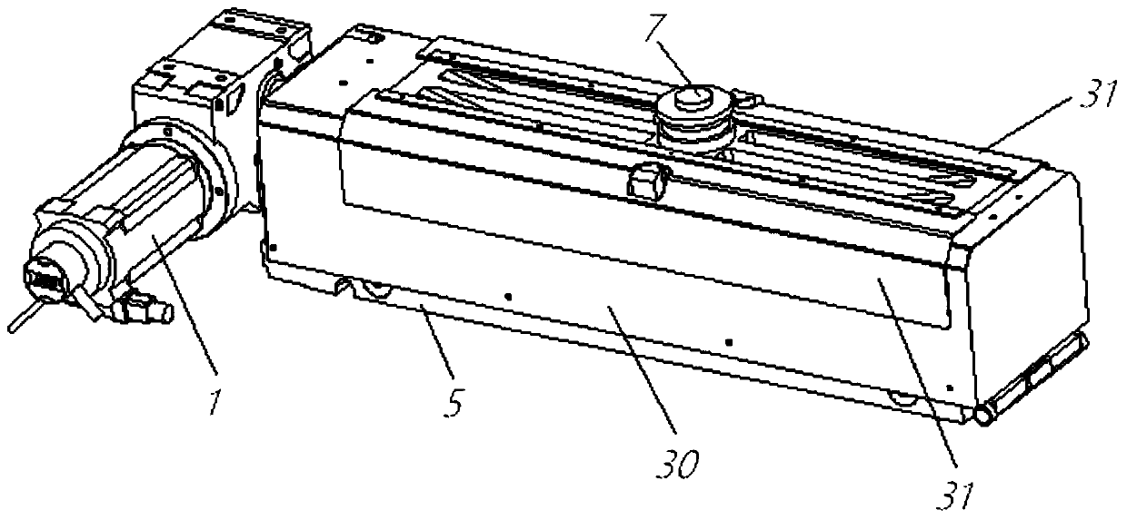
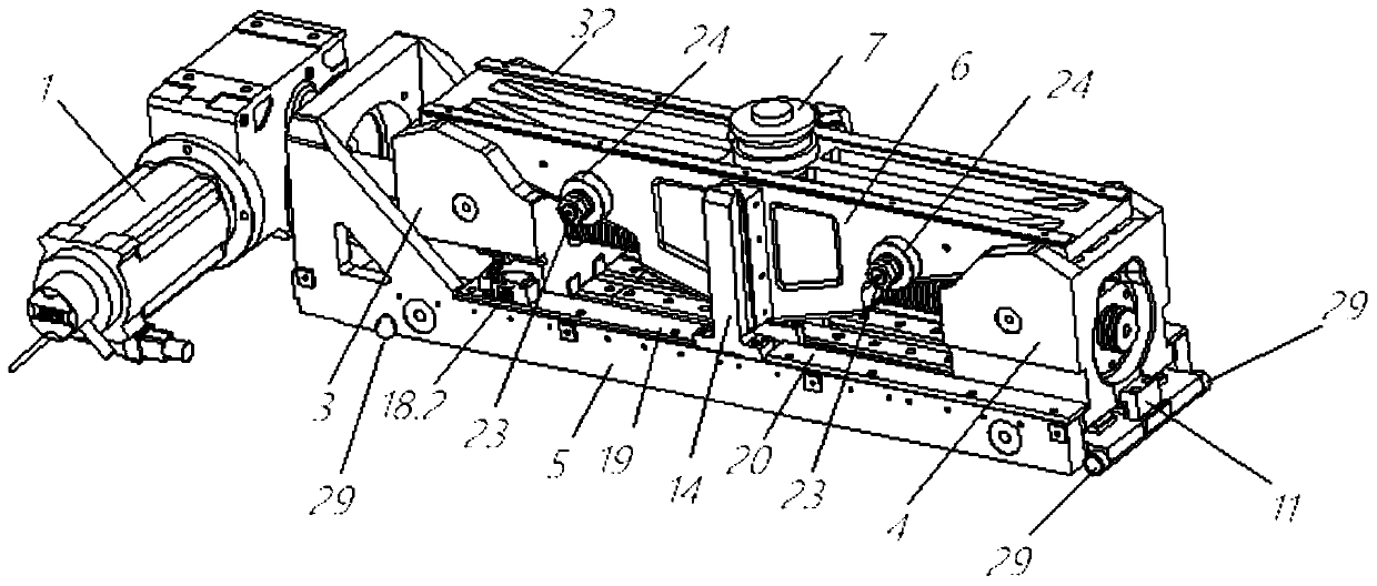
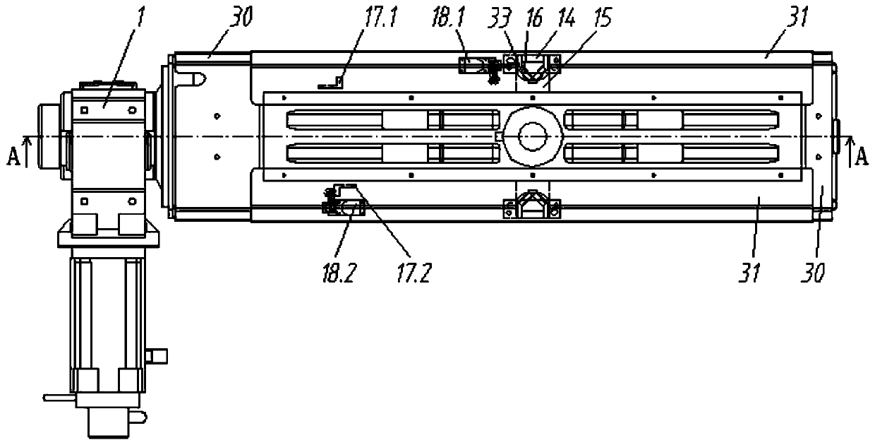
[0035] The present invention provides a servo-driven pressing device, which includes a mounting base 5 with a U-shaped groove structure. The left end of the mounting base 5 is fixed with a servo motor 1 through a vertically fixed casting structure, and a bidirectional Ball screw nut pair 2, the left end of the lead screw in the bidirectional ball screw nut pair 2 is fixedly connected to the output shaft of the servo motor 1, the thread of the left section of the lead screw in the bidirectional ball screw nut pair 2 and the thread of the lead screw The threads on the right section rotate in the opposite direction. When the screw rotates, the two nuts in the two-way ball screw nut pair 2 separate to the left and right sides or move closer to the middle, and the two nuts in the two-way ball screw nut pair 2 are fixedly connected. One cam slider, the cam slider 3 on the left and t...


PUM


Abstract

The invention provides a servo drive laminating device, which solves the problem of the power source of a special laminating machine during the laminating process; the device comprises an installationbase, a servo motor, a bidirectional ball screw nut pair, two cam sliding blocks driven by the bidirectional ball screw nut pair, a sliding block, a weighing sensor, an external reference limiting block, an internal reference limiting block, a joint injection oil cup, a longitudinal guide mechanism composed of a V-shaped convex guide rod and a V-shaped concave guide plate, a collision block, a stroke switch, a shaft, a support type roller, a straight-through injection oil cup, etc., the device can realize the different position requirements of the upward movement of a concave mold according to the product laminating process requirement, so multiple flanging can be finished and the laminating is realized; the weighing sensor feeds back the condition of the laminating force at different positions of the control system in real time.

Description

technical field [0001] The invention relates to a servo-driven pressing device, which belongs to the field of pressing equipment. Background technique [0002] Pressing equipment is divided into four categories: press die, robot roll edge press, simple press, and press machine. [0003] In the door cover line project, the customer requested that the special lamination machine be developed and manufactured abroad, and the domestic manufacturer was not qualified to undertake it. [0004] The forming process of the pressing machine and the pressing mold belongs to the large-scale simultaneous forming equipment of the circle. It is characterized by fast production rhythm, good quality stability, and relatively poor flexibility. It is more suitable for large-scale production of more than 100,000 vehicles per year. Production: Robotic roller edge pressing, which belongs to the equipment of partial gradual forming, is characterized by high flexibility, low production cycle and goo...

Claims


Application Information

Patent Timeline
Patent Type & Authority Patents(China)
IPC IPC(8): B21D19/08B21C51/00
CPCB21C51/00B21D19/08
Inventor 林琼李悦罗书保薛彦华季大龙
Owner CHINA FIRST AUTOMOBILE
Why Eureka
Try Eureka