Signal transmission method and device

A technology of signal transmission and transmission method, applied in the field of signal transmission, which can solve the problems that the terminal cannot reach the base station, the signal cannot reach the receiving end, and the transmission beam is inconsistent.

Pending Publication Date: 2018-05-29
ZTE CORP
View PDF4 Cites 24 Cited by
  • Summary
  • Abstract
  • Description
  • Claims
  • Application Information

AI Technical Summary

Problems solved by technology

If the multiplexing mode and rate matching information of the two are directly determined without considering the beam coordination problem, the signal cannot reach the receiving end due to the inconsistent understanding of the beam by both the base station and the terminal.
For example, the transmission beams of PUSCH and PUCCH are inconsistent. The base station and the terminal agree that when the PUCCH and PUSCH are transmitted in the same slot, the control information included in the PUCCH needs to be transmitted in the PUSCH, and the transmission beam of the PUSCH is uniformly used for transmission on the PUSCH channel. Data and control information included in PUCCH, but because the terminal has not received the scheduling information of PUSCH, the terminal will continue to use the original PUCCH transmit beam to send signals on PUCCH, and the base station has adjusted its receive beam to align with the PUSCH transmit beam. It will cause the signal sent by the terminal through the PUCCH to be unable to reach the base station
[0004] For the problems of beam update, multiplexing, and rate matching between the first signal and the second signal when the beams are inconsistent, no effective solution has been proposed so far

Method used


Image

  • Signal transmission method and device
  • Signal transmission method and device
  • Signal transmission method and device

Examples


Embodiment 1

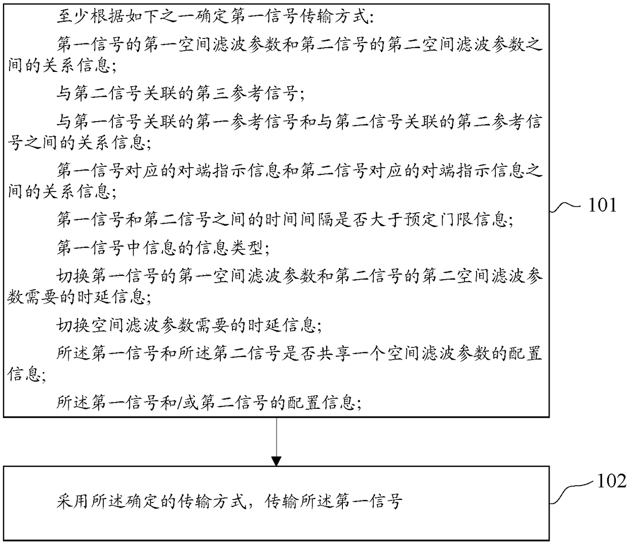
[0181] Such as figure 1 As shown, this embodiment provides a method for signal transmission, including:

[0182] Step 101, determine the first signal transmission mode at least according to one of the following:

[0183] relationship information between the first spatial filter parameter of the first signal and the second spatial filter parameter of the second signal;

[0184] a third reference signal associated with the second signal;

[0185] relationship information between a first reference signal associated with the first signal and a second reference signal associated with the second signal;

[0186] Relationship information between peer indication information corresponding to the first signal and peer indication information corresponding to the second signal;

[0187] Whether the time interval between the first signal and the second signal is greater than predetermined threshold information;

[0188] the information type of the information in the first signal;

[0...

Embodiment 2

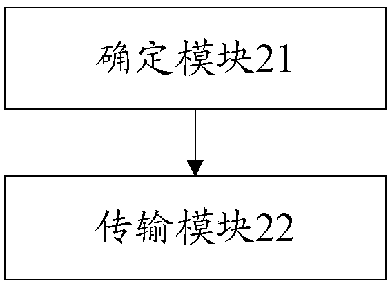
[0295] A signal transmission device such as figure 2 As shown, can include:

[0296] The determination module 21 may be configured to determine the first signal transmission mode at least according to one of the following:

[0297] relationship information between the first spatial filter parameter of the first signal and the second spatial filter parameter of the second signal;

[0298] a third reference signal associated with the second signal;

[0299] relationship information between a first reference signal associated with the first signal and a second reference signal associated with the second signal;

[0300] Relationship information between peer indication information corresponding to the first signal and peer indication information corresponding to the second signal;

[0301] Whether the time interval between the first signal and the second signal is greater than predetermined threshold information;

[0302] the information type of the information in the first s...

Embodiment 3

[0331] A signal transmission device may include:

[0332] a memory storing a signal transmission program;

[0333] A processor configured to read the signal transmission program to execute the operations of the signal transmission method in Embodiment 1.

[0334] The signal transmission device in this embodiment can be set in a terminal and / or a base station. In practical applications, the signal transmission device can be realized by a radio frequency circuit in a terminal and / or a base station.

[0335]For other technical details of this embodiment, reference may be made to Embodiment 1.


PUM


Abstract

The application discloses a signal transmission method and device. The method includes the following steps: determining a first signal transmission mode; and transmitting a first signal by using the determined transmission mode. The scheme of the application ensures that both a base station and a terminal have a consistent understanding of beams and finally enables the signal to reach an oppositeterminal.

Description

technical field [0001] The present invention relates to the communication field, in particular to a signal transmission method and device. Background technique [0002] Discussions on NR are ongoing, and an important application scenario for NR is the high-frequency beam transmission technology, especially the transmission technology based on radio frequency beams. Due to the high directivity of the beams, there is a problem when the two beams are not aligned. [0003] In a time slot (slot), when the first uplink signal and the second uplink signal need to be transmitted simultaneously, the problem of beam coordination between the two needs to be considered. If the multiplexing mode and rate matching information of the two are directly determined without considering the beam coordination problem, the signal cannot reach the receiving end due to the inconsistent understanding of the beam by both the base station and the terminal. For example, the transmission beams of PUSCH...

Claims


Application Information

Patent Timeline
Patent Type & Authority Applications(China)
IPC IPC(8): H04W72/04H04L5/00
CPCH04L5/0014H04W72/046H04B7/0695H04B7/0619H04L5/0023H04W72/23H04W72/0446
Inventor 张淑娟王瑜新鲁照华李儒岳陈艺戬高波
Owner ZTE CORP
Why Eureka
Try Eureka