[0029] In order to make the technical means, creative features, objectives and effects of the present invention easy to understand, the present invention will be further explained below in conjunction with specific embodiments.
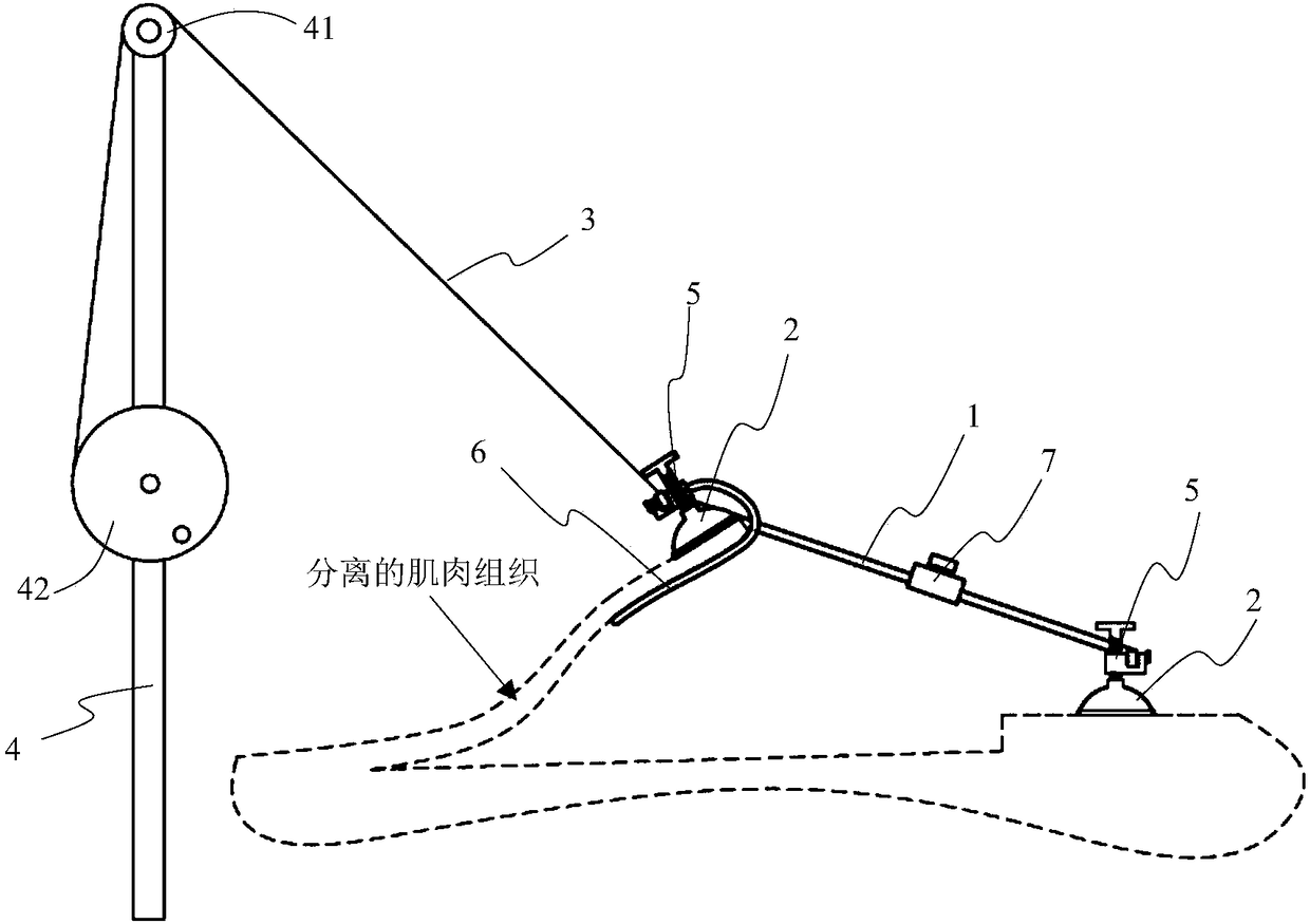
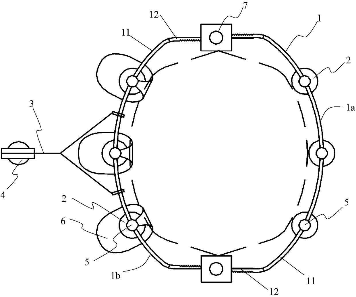
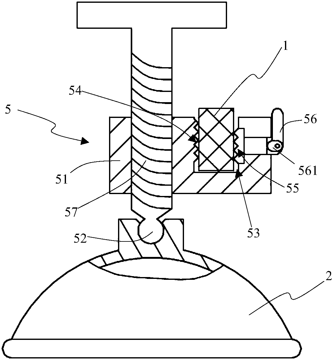
[0030] Such as Figure 1 to Figure 7 As shown, the muscle pulling device provided by this embodiment includes: a support ring 1, a suction cup 2, a pull wire 3, and a support rod 4; the support ring 1 includes: both are composed of an arc portion 11 and two arranged on the arc portion 11. The first supporting half ring 1a and the second supporting half ring 1b are composed of the connecting portion 12 at the end. The two connecting portions 12 on the same supporting half ring (including the first supporting half ring 1a and the second supporting half ring 1b) are parallel to each other Extending to the side of the center of the arc 11, the two connecting parts 12 of the two supporting half-rings are telescopically connected to form the supporting ring 1, so that the ring size of the supporting ring 1 can be adjusted; the suction cup 2 is detachably arranged here On the arc-shaped portions 11 of the first support half ring 1a and the second support half ring 1b, the cross sections of the first support half ring 1a and the second support half ring 1b are preferably rectangular, and the rectangle is in the axial direction of the support ring 1. The side length of the support ring 1 is greater than the side length in the radial direction, so that the deformation of the support ring 1 tends to occur in the radial direction, and it is difficult to occur in the axial direction. Then the suction cup 2 is located at the same end of the support ring 1 in the axial direction to perform the suction cup 2 For effective support, at least one suction cup 2 is provided on each arc portion 11 to absorb the skin tissue on both sides of the incision respectively; the support rod 4 is erected on the outside of the support ring 1, which can be placed beside the operating bed through the base cube. It can also be directly fixed to the neutral position of the operating table by a clamping device. A fixed pulley 41 is provided on the top of the support rod 4, and a cable reel 42 is provided on the support rod 4. The fixed end of the puller wire 3 is connected to the reel 42 , And store a certain length around the wire reel 42. The free end of the pull wire 3 passes through the fixed pulley 41 and then connects to the support ring 1 on the arc-shaped portion 11 of the second support half ring 1b on the side separating the muscle tissue. Perform high-position lifting; and the free end of the pull wire 3 is preferably connected to the support ring 1 through two branches to ensure that the support ring 1 can be lifted stably. The free end of the pull wire 3 can be provided with a hook for easy disassembly. And it can automatically adjust to the equilibrium position with the force of the support ring 1.
[0031] When using the above-mentioned muscle stretching device, adjust the number of suction cups 2 and the size of the support ring 1 according to different incision sizes, and then connect the skin tissues on both sides of the incision through suction cups 2, and a support ring composed of two semi-circular support half rings 1 Pull the incision open and support it, and finally lift the pull wire at a high position through the support rod 4 3 Lift the support half ring (second support half ring 1b) on the side of the muscle tissue separation, and perform the separation of the muscle tissue Pulling, the length and pulling force of the pulling wire 3 can be adjusted by rewinding the spool 42 to achieve the effect of long-term stable lifting, avoiding the occurrence of manual lifting of the muscle tissue by the medical staff for a long time, and reducing the physical strength and energy of the medical staff The huge consumption of the above, reduce the influence of human factors on the operation, and ensure the smooth progress of the operation related to muscle tissue separation.
[0032] The aforementioned suction cup 2 is detachably connected to the arc-shaped portion 11 corresponding to the supporting half ring through the adjustable connecting mechanism 5. Specifically, see image 3 , The adjustable connection mechanism 5 includes: a support block 51, a spherical connection portion 52 protruding from the lower end of the support block 51, and a support groove 53 opened on the upper surface of the support block 51, the spherical connection portion 52 is connected to the top of the suction cup 2 with a spherical hinge , So that the suction cup 2 can adjust the suction angle adaptively; the rectangular arc 11 is movably clamped into the support groove 53 along the axial direction of the support ring 1, and the suction cup 2 is located at the same end in the axial direction of the support ring 1 so that The suction cup 2 can be adjusted in position on the arc 11 of the support ring 1 according to requirements; in order to realize the fixing of the support groove 53 to the arc 11, a fixed bite is provided on the groove wall of the support groove 53 near the spherical connecting portion 52 54. A movable bite 55 is provided on the side wall of the support groove 53 away from the spherical connecting portion 52, a cam adjustment member 56 is provided on the support block 51 outside the movable bite 55, and the cam of the cam adjustment member 56 561 is in movable contact with the end of the movable bite 55 away from the tooth surface, so that when the cam adjuster 56 is pulled, the movable bite 55 can be pressed by the cam 561, and the movable bite 55 is moved to bite or loosen the support ring 1 The arc section 11. In order to facilitate the rotation of the movable cam adjusting member 56, the movable bite 55 is preferably a rubber bite, so that it has a certain degree of concession, ensuring that the cam adjusting member 56 can rotate in place and remain locked at a fixed position.
[0033] See Figure 4 , The adjustable connecting mechanism 5 on the second supporting half ring 1b on the side where the muscle tissue of the incision is separated further includes: a hook plate 6 connected to the side of the supporting block 51 away from the cam adjusting member 56, the hook plate 6 in the shape of a hook, it bypasses the suction cup 2 and extends horizontally from below one side of the cam adjuster 56, so that while the suction cup 2 absorbs and fixes the external skin tissue, the free end of the hook plate 6 can penetrate deep into the incision. The separated muscle tissue is pulled by hook to ensure effective pulling and stable maintenance of the separated muscle tissue. See Figure 5 The hook plate 6 in this embodiment is mainly composed of a hook plate body 61 made of medical rubber material and a metal skeleton 62 provided in the hook plate body 61, and the hook plate body 61 made of flexible medical rubber material is in contact with the separated muscle tissue. , To avoid damage to the muscle tissue, and at the same time, the rigidity of the metal skeleton 62 can ensure the pulling and maintaining effect of the hook plate 6 on the muscle tissue.
[0034] Considering that after the hook plate 6 is added, the space between the suction cup 2 and the hook plate 6 needs to be adapted to the thickness of the separated muscle tissue, so the gap between the suction cup 2 and the hook plate 6 should be adjustable. In this embodiment, on the adjustable connecting mechanism 5 provided with the hook plate 6, an adjusting screw 57 that is vertically screwed through the support block 51 is provided, and the position of the adjusting screw 57 corresponds to the position of the spherical connecting portion 52, The spherical connecting portion 52 is arranged at the lower end of the adjusting screw 57, and then connected to the suction cup 2 through the adjusting screw 57; rotating the adjusting screw 57 can adjust the gap between the suction cup 2 and the hook plate 6 to ensure the normal use of the hook plate 6.
[0035] See Image 6 with Figure 7 , The two end connecting portions 12 of the first supporting half ring 1a and the second supporting half ring 1b are respectively correspondingly telescopically connected through a telescopic adjustment mechanism 7. Specifically, the two correspondingly connected connecting portions 12 overlap along the radial direction of the support ring 1, and a rack 13 is provided on the side of the connecting portion 12 facing away from the overlap surface; the telescopic adjustment mechanism 7 includes: a telescopic housing 71 And the first transmission teeth 72, the second transmission teeth 73 and the driving teeth 74 arranged in the telescopic housing 71, the middle of the telescopic housing 71 is provided with a telescopic opening 75 for inserting two overlapping connecting parts 12 therethrough , The first transmission teeth 72 and the second transmission teeth 73 are respectively engaged with the rack 13 of a connecting part 12 and are arranged on both sides of the telescopic opening 75, and the driving teeth 74 are arranged above the telescopic opening 75 and simultaneously with the first transmission tooth 72 is meshed with the second transmission tooth 73, and the driving shaft 741 of the driving tooth 74 extends upward to the outside of the telescopic housing 71; rotating the driving shaft 741 can drive the driving tooth 74 to rotate, driving the first transmission tooth 72 and the second transmission tooth 73 The two connecting parts 12 are respectively driven to slide in the opposite direction to achieve the effect of telescopically adjusting the size of the support ring 1.
[0036] In this embodiment, the rotation centers of the first transmission teeth 72, the second transmission teeth 73, and the drive teeth 74 are on the same reference surface, and the reference surface is arranged at an oblique angle with the extending direction of the connecting portion 12 to reduce the position The small gear diameter reduces the width of the telescopic housing 71 and reduces the influence of the volume of the telescopic adjustment mechanism 7 on the surgical operation; at the same time, the staggered gears increase the contact point of the connecting part 12 in the axial direction, so that the support ring The structure of 1 is more stable. At the same time, on the overlapping surfaces of the two overlapping connecting portions 12, one of them is provided with a guide protrusion 14 extending in the axial direction of the connecting portion 12, and the other is provided with a guide protrusion 14 that is adapted to the guide protrusion 14 The guiding groove 15 of the two guides and limits the sliding movement of the two connecting parts 12 through the cooperation of the two, so as to further avoid the movement and misalignment of the connecting parts 12 and affect the stability of the support ring 1 structure.
[0037] In summary, the muscle pulling device using the above technical scheme can effectively pull the muscle tissue that needs to be separated. It has the outstanding advantages of long duration, high stability, and strong controllability of the pulling degree. Reduce the physical exertion of the surgeon, reduce the influence of artificial instability on the operation, and help the operation to proceed smoothly.
[0038] The above shows and describes the basic principles and main features of the present invention and the advantages of the present invention. For those skilled in the art, it is obvious that the present invention is not limited to the details of the above exemplary embodiments, and does not deviate from the spirit or basics of the present invention. In the case of features, the present invention can be implemented in other specific forms. Therefore, from any point of view, the embodiments should be regarded as exemplary and non-limiting. The scope of the present invention is defined by the appended claims rather than the foregoing description, and therefore it is intended to fall within the claims. All changes within the meaning and scope of equivalent elements of are included in the present invention. Any reference signs in the claims should not be regarded as limiting the claims involved.
[0039] In addition, it should be understood that although this specification is described in accordance with the implementation manners, not each implementation manner only includes an independent technical solution. This narration in the specification is only for clarity, and those skilled in the art should consider the specification as a whole The technical solutions in the embodiments can also be appropriately combined to form other implementations that can be understood by those skilled in the art.