An automatic centering clamping device

A clamping device and automatic centering technology, applied in vices, manufacturing tools, etc., can solve problems such as cumbersome assembly and disassembly, difficulty in controlling mutual position and size, and impact on accuracy, so as to improve the efficiency of research and development, shorten tooling manufacturing, and cost reduction effect

Active Publication Date: 2020-10-16
CHINA HANGFA GUIZHOU LIYANG AVIATION POWER CO LTD
View PDF5 Cites 2 Cited by
  • Summary
  • Abstract
  • Description
  • Claims
  • Application Information

AI Technical Summary

Problems solved by technology

[0004] (1) During the manufacturing process, the axis 1a and the surface 1b, the axis 4a and the surface 4b, the hole 7a and the plane 7b belong to the transition between the cylindrical surface and the plane, making it difficult to control their mutual position and size;
[0005] (2) Assembly and disassembly are cumbersome and inconvenient to adjust
Especially for the guide seat 7, the second assembly after disassembly will inevitably change the position, which will have a certain impact on the accuracy after assembly, and then affect the processing accuracy of the product

Method used


Image

  • An automatic centering clamping device
  • An automatic centering clamping device
  • An automatic centering clamping device

Examples


Embodiment Construction

[0029] The technical solution of the present invention is further described below in conjunction with the accompanying drawings, but the scope of protection is not limited to the description.

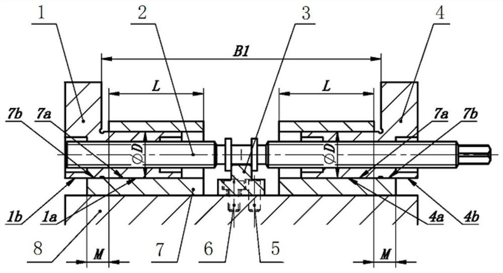
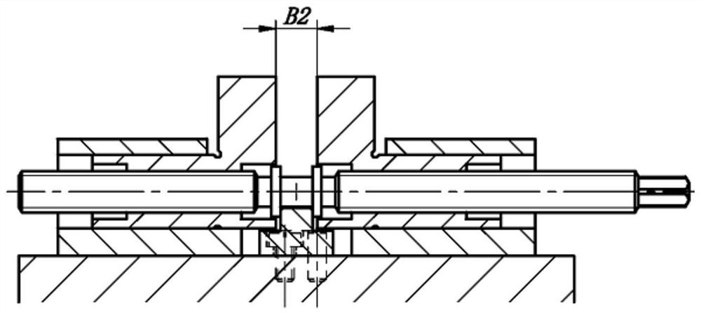
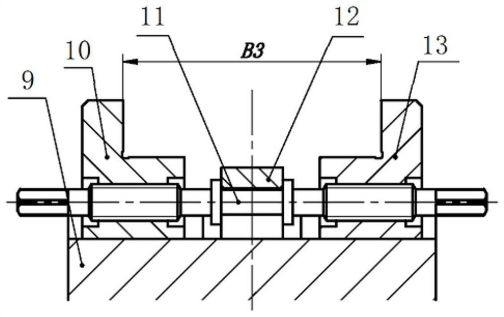
[0030] Such as Figure 3 to Figure 9 As shown, a kind of automatic centering clamping device described in the present invention comprises base plate A9, left clamping block 10, double-ended screw rod A11, brake block A12, right clamping block 13, left guide plate 14 and right guide plate 15, so The left guide plate 14 and the right guide plate 15 are all installed on the base plate A9 by cylindrical pins A16 and screws B19, and the left guide plate 14 and the right guide plate 15 are installed on the base plate A9 to form a T-shaped guide groove, and the two ends of the double-ended screw A11 are respectively Screw into the left clamping block 10 and the right clamping block 13 to form an assembly, which is installed in the T-shaped guide groove formed by the left guide plate 14, the ri...


PUM


Abstract

The invention discloses an automatic centering and clamping device. The automatic centering and clamping device comprises a bottom plate A, a left clamping block, a dual-head screw A, a brake block A,a right clamping block, a left guide plate and a right guide plate; the left guide plate and the right guide plate are each mounted on the bottom plate A through a cylindrical pin A and a bolt B, theleft guide plate and the right guide plate are mounted on the bottom plate A to form a T-shaped guide groove, the two ends of the dual-head screw A are screwed into the left clamping block and the right clamping block to form an assembly, the assembly is arranged in the T-shaped guide groove formed by the left guide plate, the right guide plate and the bottom plate A, the brake block A is arranged in the middle of the dual-head screw A in a sleeved manner, and is arranged on the bottom plate A through a cylindrical pin B and a bolt A, the brake block A is located between the left clamping block and the right clamping block, and the brake block is of a covering type buckle saddle structure. An optimized manufacturing, assembling, detaching and adjusting scheme can be provided for the automatic centering and clamping device, the tool manufacturing and repair time can be shortened, cost is reduced, and the developing work efficiency is improved.

Description

technical field [0001] The invention belongs to the technical field of mechanical processing, relates to the design technology of aero-engine tooling tools, and in particular relates to an automatic centering clamping device. Background technique [0002] At present, the existing centering clamping devices are mainly vise-type clamps, such as figure 1 , figure 2 As shown, the vise-type fixture is composed of a left jaw 1, a double-ended screw 2, a brake block 3, a right jaw 4, a cylindrical pin 5, a screw 6, a guide seat 7 and a base plate 8. The guide seat 7 and the brake block 3 are installed and connected on the base plate 8 through the cylindrical pin 5 and the screw 6; the left jaw 1, the right jaw 4 and the guide seat 7 cooperate with the shaft 1a and the shaft 4a through the hole 7a in the L range, and the The M range is fitted by the plane 7b, the surface 1b and the surface 4b, so that the left jaw 1 and the right jaw 4 move on the guide seat 7 without turning ove...

Claims


Application Information

Patent Timeline
Patent Type & Authority Patents(China)
IPC IPC(8): B25B1/10B25B1/24
CPCB25B1/103B25B1/24
Inventor 邹朝亮解为刚
Owner CHINA HANGFA GUIZHOU LIYANG AVIATION POWER CO LTD
Why Eureka
Try Eureka