Hydraulic machine
A technology of hydraulic machinery and guide vanes, applied in the field of hydraulic machinery, can solve the problems of increased loss, increased flow loss of guide vanes 120, flow turbulence, etc., and achieve the effect of reducing flow loss and suppressing horseshoe-shaped vortices
- Summary
- Abstract
- Description
- Claims
- Application Information
AI Technical Summary
Problems solved by technology
Method used
Image

Examples
no. 1 approach
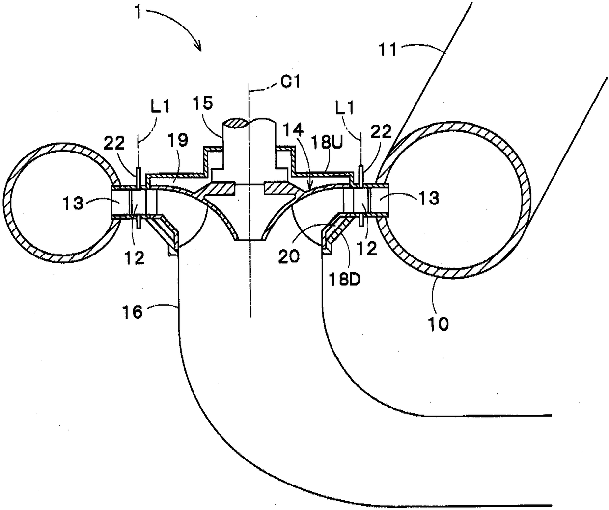
[0031] figure 1 It shows the Francis-type pump-turbine 1 as an example of the hydraulic machine according to the first embodiment of the present invention. In addition, in the following description, the Francis-type pump-turbine 1 is simply referred to as the hydraulic turbine 1 . The water turbine 1 includes a casing 10 into which water flows through an iron pipe 11 from an upper tank (not shown), a plurality of guide vanes 12 , a plurality of stator vanes 13 , and a flow channel 14 .
[0032] In the hydraulic turbine 1 , during the operation of the hydraulic turbine, the water from the casing 10 flows into the flow channel 14 through the stationary blade row flow path constituted by the guide vanes 12 and the stator vanes 13 . Thereby, the flow channel 14 rotates around the flow channel rotation axis C1. In addition, in the following description, when it is only called the axial direction, it means that the direction is the direction on the flow path rotation axis C1 or t...
no. 2 approach
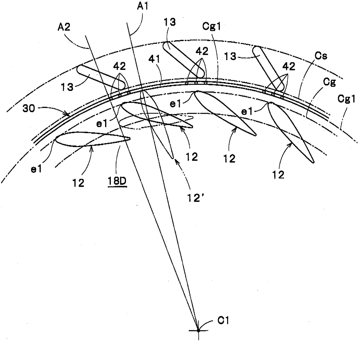
[0048] Next, the second embodiment will be described. Figure 4 It is the figure which looked at the stator vane, the guide vane, and the lower cover of the Francis-type pump-turbine which concerns on 2nd Embodiment along the rotation axis of a flow passage. In this embodiment, the same reference numerals are given to the same components as those of the above-described first embodiment, and descriptions thereof will be omitted.
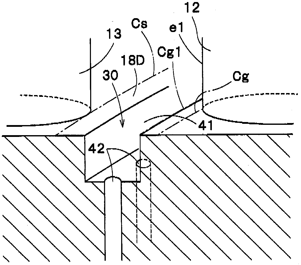
[0049] In the present embodiment, the configuration of the groove 41 is different from that of the first embodiment. That is, as Figure 4 As shown, the groove 41 in the present embodiment is formed on an arc centered on the guide vane rotation axis L1 passing between the adjacent guide vanes 12 and the stator vanes 13, and is formed, for example, in a Figure 4 on the arc of the part of the circle indicated by the dotted line. The grooves 41 are provided for each combination of the adjacent guide vanes 12 and the stator vanes 13 , and each groove ...
no. 3 approach
[0053] Next, a third embodiment will be described. Figure 5 It is a meridian cross-sectional view of the Francis-type pump-turbine according to the third embodiment. In this embodiment, the same components as those of the above-described embodiments are denoted by the same reference numerals, and the description thereof will be omitted.
[0054] In the above-described first embodiment, the suction hole 42 sends the suctioned water to the outside of the turbine 1 as an example, but in this embodiment, the water suctioned by the suction hole 42 is sent to the flow passage side pressure chamber 20 . Specifically, Figure 5 As shown, the suction mechanism 30 has a pipe portion 43 that communicates the suction hole 42 with the flow passage side pressure chamber 20 . In addition, the arrangement|positioning structure of the suction hole 42 is the same as that of 1st Embodiment.
[0055] Such an embodiment can also suppress the generation of horseshoe-shaped vortices that may be ...
PUM
 Abstract
Description
Claims
Application Information
 - R&D Engineer
- R&D Manager
- IP Professional
- Industry Leading Data Capabilities
- Powerful AI technology
- Patent DNA Extraction
Browse by: Latest US Patents, China's latest patents, Technical Efficacy Thesaurus, Application Domain, Technology Topic.
© 2024 PatSnap. All rights reserved.Legal|Privacy policy|Modern Slavery Act Transparency Statement|Sitemap